- Catalogs
- Littelfuse
- Fuse Fundamentals
- Company
- Products
- Catalogs
- News & Trends
- Exhibitions
Fuse Fundamentals
1 /20Pages

Fuse Fundamentals
1 /20Pages
Catalog excerpts

At the Heart of Electrical Systems, Fuses Keep Operations Live Littelfuse* Expertise Applied | Answers Delivered
Open the catalog to page 1
FUSE FUNDAMENTALS
Open the catalog to page 2
Introduction All electrical systems eventually experience overcurrents. Unless removed in time, even moderate overcurrents will quickly overheat system components and damage the insulation, conductors and equipment. Large overcurrents can melt conductors, burn insulation, and produce magnetic forces capable of bending and twisting bus bars. High currents can pull cables from their terminals and crack insulators and spacers. The fires, explosions, and poisonous fumes caused by an uncontrolled overcurrent can injure and kill personnel. These injuries and deaths are easily avoidable with sufficient...
Open the catalog to page 3
FUSE FUNDAMENTALS system may have a load impedance of 0.005 ohms or less. The longer it takes for a protective device to trip, the larger the arc flash will be. This is one reason it is so important to select the proper fuse for the application. To compare these two scenarios, apply Ohm’s Law (current = voltage ÷ resistance). Thus, a 480-V single-phase circuit with a 10-ohm load impedance will draw 48 A: Magnetic stress (force) is a function of the peak current squared. Fault currents can exert magnetic stress that are high enough to damage insulation, pull conductors from terminals, and stress...
Open the catalog to page 4
Effect of Ambient Temperature Fuses are a thermal device that are impacted by ambient temperatures. Elevated ambient temperatures can effectively "derate" a fuse's current carrying capacity to be much less than its marked rating. There are published derating curves that should be considered. Current Limitation Current-limiting fuses greatly minimize the total destructive heat energy (I2t) to the circuit and its components. Current-limiting fuses open and clear short circuits in less than 180 electrical degrees (the first half electrical cycle). NEC Article 240—Overcurrent Protection says that...
Open the catalog to page 5
FUSE FUNDAMENTALS Interrupting Rating A fuse's interrupting rating is the highest available fault current the fuse can safely interrupt at its rated voltage under standardized test conditions. All UL Listed fuses must safely interrupt all overcurrents between its current rating and its interrupting rating. Standard UL fuses are available with interrupting ratings up to 300 000 A. According to NEC Article 110.9: Equipment intended to interrupt current at fault levels shall have an interrupting rating at nominal circuit voltage at least equal to the available fault current at the line terminals...
Open the catalog to page 6
Time-Delay (SLO-BLO®) Fuses By mitigating nuisance fuse openings and limiting the frequency of downtime incidents, time-delay fuses provide the best overall protection for both motor and general-purpose circuits. Many UL Class CC, CD, G, J, L, RK5 and RK1 fuses, plus some of the miscellaneous UL Listed fuses are time-delay. You can identify time-delay fuses by looking on the label for terms such as time-delay, T-D, D, or other similar markings. Minimum-time delay requirements vary by the fuse class. UL standards require Class J, Class RK5, and Class RK1 to carry 500% rated current for a minimum...
Open the catalog to page 7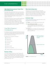
FUSE FUNDAMENTALS High-Speed Semiconductor Fuses (Very Fast-Acting Fuses) Mounting Configuration Depending on the fuse block design, you should also consider how the fuse block is mounted or inserted into the panel. Historically, fuse blocks screwed into the back of the panel, but many newer designs have a DIN-rail mounting capability. The DIN-rail mounting feature allows the blocks to be quickly installed and removed from the rails. High-speed semiconductor fuses (also known as very fastacting fuses, high-speed fuses, or ultra-rapid fuses) are for a limited number of applications. High-speed...
Open the catalog to page 8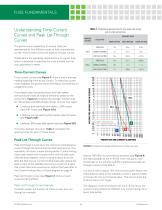
Understanding Time-Current Curves and Peak Let-Through Curves The performance capabilities of various fuses are represented by two different types of fuse-characteristic curves: time-current curves and peak let-through curves. These define the operating characteristics of a given fuse, which is essential in selecting the most suitable fuse for your application's needs. Time-Current Curves Time-current curves (see Figure 2) show a fuse's average melting (opening) time at any current. To make the curves more readable, the performance information is presented on a logarithmic plot. Time-delay fuses,...
Open the catalog to page 9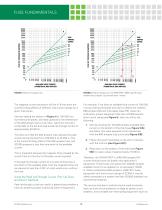
AVAILABLE FAULT CURRENT SYMMETRICAL RMS AMPERES AVAILABLE FAULT CURRENT SYMMETRICAL RMS AMPERES FIGURE 4. Peak Let-through curves. FIGURE 5. Peak let-through curve for POWR-PRO® LLNRK Class RK1 dualelement fuses using the "up-over-and-down” method. The diagonal curves that branch off the A-B line show the current-limiting effects of different fuse current ratings for a given fuse series. Start by reading the bottom of Figure 4 at 100 000 rms symmetrical amperes, and read upwards to the intersection of the 200-ampere fuse curve. Now, read from this point horizontally to the left and read a peak...
Open the catalog to page 10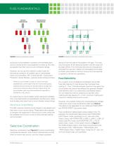
FUSE FUNDAMENTALS WITHOUT COORDINATION WITH SELECTIVE COORDINATION FIGURE 6. Selective coordination example. FIGURE 7. Example of selectively coordinated fused system. bus ducts) to be installed in systems with available shortcircuit currents (known as prospective currents by IEC) that are greater than their short-circuit (withstand) ratings. device on the line side of the problem will open. This way, only the section of the electrical system with the issue will be taken offline. This minimizes the amount of equipment removed from service, makes the overloaded circuit easier to locate, and creates...
Open the catalog to page 11
TABLE 2. Fuse Coordination Table. Selecting the correct fuse current ratio to maintain selectively coordinated systems. (Ratios are expressed as line-side fuse to load-side fuse.) The coordination table also shows that the Littelfuse LLSRK_ID series time-delay RK1 feeder and branch circuit fuses coordinate at a 2:1 ratio with the Class L feeder fuses, so the entire system in Figure 7 can be considered completely coordinated. Circuit-Breaker Coordination As a result of the numerous types of circuit breakers and circuit breaker trip units available in the market, developing a coordinated circuit...
Open the catalog to page 12All Littelfuse catalogs and technical brochures
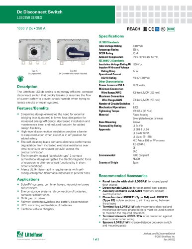 Dc Disconnect Switches
2 Pages
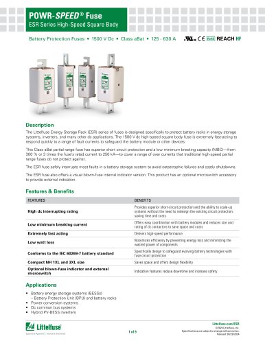 ESR_Fuse_Datasheet
9 Pages
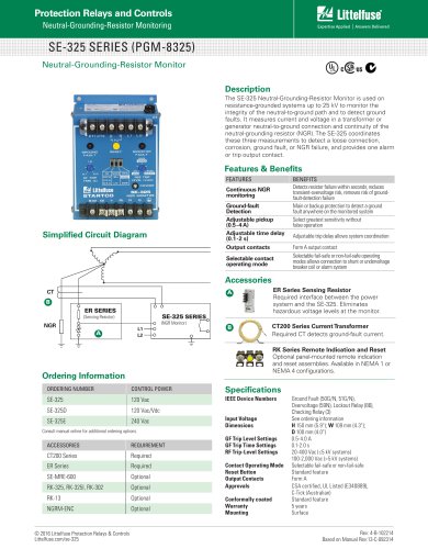 SE-325 SERIES (PGM-8325)
1 Page
 SE-CS10 SERIES
2 Pages
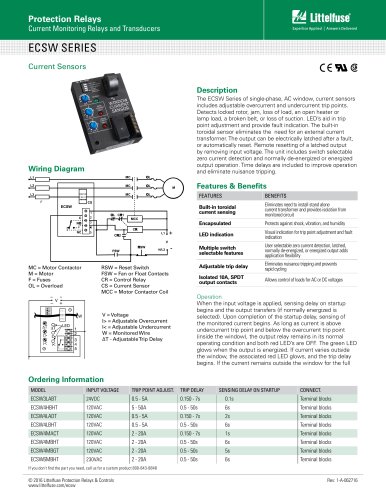 ECSW SERIES
3 Pages
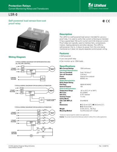 LSR-0
LSR-01 Page
 LSRU SERIES
2 Pages
 LSRX / LSRX-C SERIES
2 Pages
 50R-400-ALT
1 Page
 ALT SERIES
2 Pages
 QJxx30LH4 series
6 Pages
 Thyristors QJ8012xHx Series
8 Pages
 30KPA-HRA Series
7 Pages
 AK1-Y Series
4 Pages
 QJxx40xx Series
8 Pages
 TS Series
11 Pages
 Littelfuse SIDACtor Products Catalog
239 Pages
 Electronic Fuse Products Catalog
409 Pages
 Passenger Car Catalog
60 Pages
 Polyfuse PPTC Catalog
128 Pages
 POWRGARD Electrical Product Catalog
202 Pages
 Protection Relays SSAC Catalog
524 Pages
 Sensors Products Catalog
20 Pages
 SIDACtor Catalog
239 Pages
 TVS Diode Array (SPA) Catalog
215 Pages
 Varistors Catalog
254 Pages
 SOLAR PRODUCTS CATALOG
28 Pages
 MP8000
2 Pages
 MicroPlex® SSR18 AND SSR30
2 Pages
 606 Series
3 Pages
 ST Series
3 Pages
 885 Series Fuse
3 Pages
 MicroPlex® 7X, 7H, & 7L
2 Pages
 TPSMB Series
6 Pages
 TPSMD Series
6 Pages
 ISOBUS SYSTEM
2 Pages
 POLYFUSE®
6 Pages
 Passenger Car Solutions
60 Pages
 TVS Diode Catalog
174 Pages
 Switching Thyristor Product Catalog
442 Pages


Archived catalogs
 HIGH-SPEED SEMICONDUCTOR
72 Pages
 INDUSTRIAL CIRCUIT PROTECTION
292 Pages
 Power Semiconductor & IC
133 Pages
 SURGE PROTECTIVE DEVICES
32 Pages
 ELECTRICAL COILS
2 Pages
 PRODUCTS FOR AGRICULTURE
36 Pages
 CIRCUIT PROTECTION
15 Pages
 MSL Classification
2 Pages
 AFTERMARKET PRODUCTS CATALOG
136 Pages
 AFTERMARKET PRODUCTS CATALOG 2018
132 Pages
 Littelfuse Thyristor Catalog
467 Pages


- Temperature probe
- Transformer
- Dry transformer
- Surge protector
- Resistance temperature sensor
- Proximity switch
- Level probe
- Liquid level sensor
- Switching relay
- DIN rail lightning arrester
- Cylindrical proximity sensor
- Class II surge protector
- Panel panel meter
- Isolator switch
- Current transformer
- Protection relay
- Position transducer
- Analog level sensor
- Encapsulated transformer