
Catalog excerpts
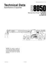
Specifications & Capacities Telescopic Boom Rough Terrain Crane 50 US ton 50 metric ton CAUTION: This material is supplied for reference use only. Operator must refer to in-cab Crane Rating Manual and Operator’s Manual to determine allowable crane lifting capacities and assembly and operating procedures.
Open the catalog to page 1
Link‐Belt Cranes
Open the catalog to page 2
Table Of Contents Boom, Attachments, and Upper Structure . . . . . . . . . . . . . . . . . . . . . . . . . . . . . . . . . . . . . . . . . . . . . . . . . . . . Boom . . . . . . . . . . . . . . . . . . . . . . . . . . . . . . . . . . . . . . . . . . . . . . . . . . . . . . . . . . . . . . . . . . . . . . . . . . . . . . . . . . . . Boom . . . . . . . . . . . . . . . . . . . . . . . . . . . . . . . . . . . . . . . . . . . . . . . . . . . . . . . . . . . . . . . . . . . . . . . . . . . . . . . . . . . Boom Head . . . . . . . . . . . . . . . . . . . . . . . . . . . . . . . . . . . . . . . . ....
Open the catalog to page 3
Fly Attachment Lift Capacity Charts - Optional . . . . . . . . . . . . . . . . . . . . . . . . . . . . . . . . . . . . . . . . . . . . . . . Fully Extended Outriggers - 360° Rotation . . . . . . . . . . . . . . . . . . . . . . . . . . . . . . . . . . . . . . . . . . . . . . . . . . . 110 ft Main Boom Length 2° Fly Offset . . . . . . . . . . . . . . . . . . . . . . . . . . . . . . . . . . . . . . . . . . . . . . . . . . . . . . . . . . . . . . . . . . . . . . . . . . . . . 110 ft Main Boom Length 20° Fly Offset . . . . . . . . . . . . . . . . . . . . . . . . . . . . . . . . . . . . . . . . ....
Open the catalog to page 4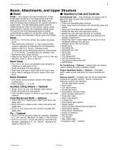
■ Boom Design — Four section, box type construction of high tensile steel consisting of one base section and three telescoping sections. The vertical side plates have diamond shaped steel impressions for superior strength to weight ration. The first telescoping section extends independently by means of one double-acting, single stage hydraulic cylinder with integrated holding valves. The second and third telescoping sections extend proportionally by means of one double-acting, single stage cylinder with integrated holding valves and cables. Boom • 35 ft 6 in-110 ft (10.8-33.5m) four section...
Open the catalog to page 5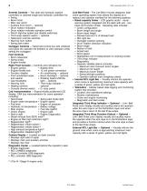
Engine ignition Engine throttle lock Function disable Front windshield wiper and washer Cab floodlights Warning horn Heating controls Console dimmer switch Swing park brake light Engine speed Engine oil pressure Battery voltage Fuel rate (gal/hr) Engine load Engine Diagnostics Armrest Controls — Two dual axis hydraulic joystick controllers or optional single axis hydraulic controllers for: • Swing • Boom hoist • Main rear winch • Auxiliary front winch - optional • Drum rotation indication • Drum rotation indicator activation switch • Winch high/low speed and disable switch(es) • Third wrap...
Open the catalog to page 6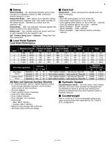
■ Swing Motor/Planetary — Bi-directional hydraulic swing motor mounted to a planetary reducer for 360° continuous smooth swing at 2.5 rpm. Swing Park Brake - 360°, electric over hydraulic, (spring applied/hydraulic released) multi-disc brake mounted on the speed reducer. Operated by a switch from the operator's cab. Swing Brake - 360°, foot operated, hydraulic applied disc brake mounted to the speed reducer. Swing Lock - Two-position swing lock (boom over front or rear) operated from the operator's cab. 360° Positive Swing Lock — Optional - Meets New York City requirement. ■ Load Hoist...
Open the catalog to page 7
Carrier ■ General • 10 ft 10.5 in (3.31m) wide • 12 ft 7 in (3.83m) wheelbase (centerline of first axle to centerline of second axle). Frame - Box-type, torsion resistant, welded construction made of high tensile steel. Equipped with front and rear towing and tie-down lugs, tow connections, and access ladders. ■ Outriggers Boxes - Two double box, front and rear welded to carrier frame. Beams and Jacks - Four single stage beams with Confined Area Lifting Capacities (CALC™) provide selectable outrigger extensions of full, intermediate, and retracted. Hydraulically controlled from the...
Open the catalog to page 8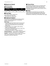
■ Fuel Tank One 75 gallon (283.9L) capacity tank Diesel Exhaust Fluid (DEF) tank • One 5 gal (18.9L) capacity tank ■ Hydraulic System All functions are hydraulically powered allowing positive precise, control with independent or simultaneous operation of all functions. Main Pumps • Three fixed displacement gear pumps for the main and auxiliary winches, swing, boom hoist, and telescope circuits with a manual disconnect to aid during cold weather starts. • One gear pump for the outriggers, power steering, brakes, and telescope circuits. • One pressure compensated piston pump is used in the...
Open the catalog to page 9
Link-Belt Cranes
Open the catalog to page 10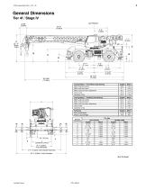
Turning Radius - Front Wheel (4x2) Steering Wall to wall over carrier Wall to wall over boom Wall to wall over boom attachment Turning Radius - All Wheel (4x4) Steering English 39’ 0” English Metric Wall to wall over carrier Fully Retracted 17’ 6” (5.33m) Intermediate Extended — 22’ 6” (6.86m) Fully Extended — Wall to wall over boom Wall to wall over boom attachment Tail Swing With counterweight English Metric Without counterweight Not To Scale Link-Belt Cranes
Open the catalog to page 11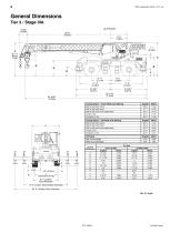
General DimensionsTier 3 / Stage IIIA 31.55” Turning Radius - Front Wheel (4x2) Steering Wall to wall over carrier Wall to wall over boom Wall to wall over boom attachment Turning Radius - All Wheel (4x4) Steering Wall to wall over carrier Wall to wall over boom Wall to wall over boom attachment Tail Swing With counterweight Without counterweight
Open the catalog to page 12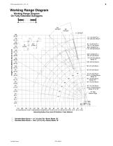
Working Range Diagram Working Range Diagram On Fully Extended Outriggers Height In Feet (Meters) Above Ground 28.5' (8.69m) Fly + 90' (27.4m) Boom 110' (33.53m) Boom Mode “B” Denotes Main Boom + 51' (15.5m) Fly-Boom Mode “B” Denotes Main Boom + 28.5' (8.7m) Fly-Boom Mode “B” Link‐Belt Cranes
Open the catalog to page 13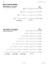
Inner Mid Section 288” (7.57m) Stroke Boom Mode “B” (Standard) lnner mid, outer mid, and tip sections f#0000 0000000000000000 )“| 100000 oootxj^oooo ooo^ooo ooo^boOQ 0000000000000000 )j j-^ ooooo ooooooooo^oooo ooooooo^ooo oooooo^OQOO 0000000QQ0QQQQQQ )°] j^* ooooo ooooooooooooo^oooo oooooooooog^ooo oooooooooo^OQOQ 0000000000000000 )°] ooooo ooooooooooooooodo^ooo ooooooooooooo^ooo ooooooooooooo^OQOO 0000000000000000 )°] j^ooooo" ooooooooooooooooooooo ^0000 0000000000000000(^000 OOOOOOOOOOOOOOOOt^QQQQ OOOOOOOQOOOOOOOO )°) Tip Section Outer Mid Section Inner Mid Section Base Section
Open the catalog to page 14All Link-Belt catalogs and technical brochures
-
TCC-800
2 Pages
-
TCC-550
2 Pages
-
218|V
8 Pages
-
120|TT
2 Pages
-
CRANE GUIDE-2023
8 Pages
-
120|HT
32 Pages
-
65|HT
8 Pages
-
HTC-8640 SL
8 Pages
-
RTC-80160 SII
8 Pages
-
100|RT
8 Pages
-
85|RT
2 Pages
-
HTC8675 SERIES II
76 Pages
-
298 series2
8 Pages
-
HTT-8675 Series II
8 Pages
-
138 HSL
8 Pages
-
175|AT
4 Pages
-
120|RT
2 Pages
-
TCC-2500
8 Pages
-
TCC-1200
8 Pages
-
228 HSL
8 Pages
-
HTT-86110
12 Pages
-
110|RT
8 Pages
-
75|RT
2 Pages
-
RTC-80150
6 Pages
-
RTC-80130
6 Pages
-
RTC-8090 Series II
2 Pages
-
RTC-8080
2 Pages
-
RTC8065
2 Pages
-
TCC 500
2 Pages
-
TCC-750
2 Pages
-
238 HSL Series
6 Pages
-
298 Hylab HSL Series
6 Pages
-
ATC 3210
8 Pages
-
Link-Belt RTC-8050 Series II
2 Pages
-
Link-Belt RTC-8030 Series II
2 Pages
-
TCC-1100
6 Pages
-
298 HSL
6 Pages
-
238 HSL
2 Pages
-
218 HSL
6 Pages
-
108 HYLAB 5
6 Pages
-
ATC-3275
8 Pages
-
HTT-86100
6 Pages
-
HTC-3140
2 Pages
-
HTC-86100
2 Pages
-
HTC-8660 Series II
4 Pages
-
RTC-80130 Series II
2 Pages
-
RTC-80110 Series II
6 Pages
-
RTC-8065 Series II
2 Pages
-
Product Guide
8 Pages
Archived catalogs
-
Crane guide
8 Pages
-
Link-Belt RTC-8075
2 Pages


