
Catalog excerpts
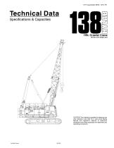
Technical Data Specifications & Capacities CAUTION: This material is supplied for reference use only. Operator must refer to in-cab Crane Rating Manual and Operator's Manual to determine allowable crane lifting capacities and assembly and operating procedures. Link‐Belt Cranes
Open the catalog to page 1
Link‐Belt Cranes
Open the catalog to page 2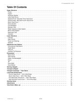
Table Of Contents Upper Structure . . . . . . . . . . . . . . . . . . . . . . . . . . . . . . . . . . . . . . . . . . . . . . . . . . . . . . . . . . . . . . . . . . . . . . . . . . . . Frame . . . . . . . . . . . . . . . . . . . . . . . . . . . . . . . . . . . . . . . . . . . . . . . . . . . . . . . . . . . . . . . . . . . . . . . . . . . . . . . . . . . . Engine . . . . . . . . . . . . . . . . . . . . . . . . . . . . . . . . . . . . . . . . . . . . . . . . . . . . . . . . . . . . . . . . . . . . . . . . . . . . . . . . . . . Hydraulic System . . . . . . . . . . . . . . . . . . . . . . . ....
Open the catalog to page 3
Tube Boom Working Range Diagram . . . . . . . . . . . . . . . . . . . . . . . . . . . . . . . . . . . . . . . . . . . . . . . . . . . . . . . . Tube Boom Load Chart . . . . . . . . . . . . . . . . . . . . . . . . . . . . . . . . . . . . . . . . . . . . . . . . . . . . . . . . . . . . . . . . . . . . . Angle Boom Make-up . . . . . . . . . . . . . . . . . . . . . . . . . . . . . . . . . . . . . . . . . . . . . . . . . . . . . . . . . . . . . . . . . . . . . Angle Boom Working Range Diagram . . . . . . . . . . . . . . . . . . . . . . . . . . . . . . . . . . . . . . . . . . . . . . . . . . . ....
Open the catalog to page 4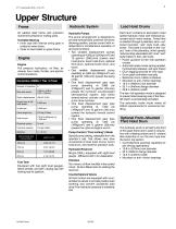
Upper Structure Frame Hydraulic System All welded steel frame with precision machined surfaces for mating parts. Turntable Bearing • Inner race with internal swing gear is bolted to lower frame. • Outer is race bolted to upper frame. Engine Engine Full pressure lubrication, oil filter, air cleaner, hour meter, throttle, and electric control shutdown. Fuel Tank Equipped with fuel sight level gauges, flame arrester, and self-closing cap with locking eye for padlock. Hydraulic Pumps The pump arrangement is designed to provide hydraulically powered functions allowing positive, precise control...
Open the catalog to page 5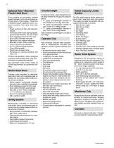
Optional Rear-Mounted Fourth Hoist Drum Drum contains an axial piston, variable speed hydraulic motor with individual automatic winch motor brakes. Power flow is directed through a patented, semi-outboard mounted, “wet” style multi-disc brake. • Power up/down & free-fall operation modes • Automatic brake mode (spring applied, hydraulically released, wet type brake) • Drum lagging grooved for wire rope • Drum pawl controlled manually • Electronic drum rotation indicators • Mounted on anti-friction bearings • 18.0 in (457mm) root diameter • 30.7 in (780mm) flange diameter • 19 in (483mm)...
Open the catalog to page 6
Carbody Lower Frame All welded high strength steel [65,000 psi (448.16MPa) yield] box construction frame with precision machined surfaces for turntable bearing and rotating joint. • 9 ft 2.3 in (2.80m) overall width • 11 ft 10.9 in (3.63m) overall length Side Frames Side Frames All welded, precision machined, steel frames can be hydraulically extended and retracted by a hydraulic cylinder mounted in the lower frame. • 14 ft (4.27m) extended gauge • 8 ft 11 in (2.72m) retracted gauge • 20 ft 2 in (6.15m) overall length • 36 in (0.91m) wide track shoes • Sealed (oil filled) idler and drive...
Open the catalog to page 7
Angle Boom 40-150 ft (12.19-45.72m) Basic Angle Boom 40 ft (12.19m) two-piece design that utilizes a 20 ft (6.10m) base section and a 20 ft (6.10m) top section with in-line connecting pins on 45.7 in (1.16m) wide and 45.7 in (1.16m) deep centers. • Boom foot on 43.5 in (1.10m) centers • 4 in x 4 in x 0.38 in (10.16cm x 10.16cm x 0.97cm) angle chords • Lugs on base section to attach carrying links • Deflector roller on top section • Permanent skid pads mounted on top section to protect head machinery • Rigid sheave guards • Four, 18 in (0.46m) root diameter steel sheaves mounted on sealed...
Open the catalog to page 8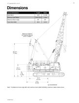
Dimensions English Minimum Load Radius Maximum Boom Angle Track Shoe Width General Dimensions Basic Boom Maximum height of live mast from ground is 29' 2” (8.89m) 3' 8” (1.12m) 12' 2” (3.71m) 14' 2” (4.32m) C OF ROTATION L Note: **@ Maximum boom angle (80°) with maximum boom [200 ft (60.96m)], maximum rotation radius occurs.
Open the catalog to page 9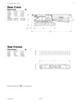
Weight: Tube Boom 89,923 lb Angle Boom 90,674 lb Number inside black circle V = # of components
Open the catalog to page 11
Upper Counterweights “A” Slab Counterweight O Length 46 in (1.17m) Width 10 ft 6 in (3.20m) “B” Slab Counterweight O Length 46 in (1.17m) “C” Slab Counterweight O Length 43.50 in (1.10m) Number inside black circle V = # of components
Open the catalog to page 12
Boom 54 in (1.37m) x 44 in (1.12m) Tube Boom Extensions 10 ft (3.05m) Extension Weight: 514 lb (233kg) 45.7 in (1.16m) x 45.7 in (1.16m) Angle Boom Extensions 58.50” (1.49m)
Open the catalog to page 13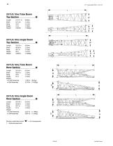
20 ft (6.10m) Tube Boom Top SectionO Length 21 ft 11 in (6.68m) 20 ft (6.10m) Angle Boom Top SectionO Length Width Deep Height Weight 20 ft (6.10m) Tube Boom Base SectionO Weight w/o Self Assembly w/ Self Assembly 20 ft (6.10m) Angle Boom Base SectionO Weight w/o Self Assembly w/ Self Assembly r* W 1_3 Hi Number inside black circle V = # of components * - Optional equipment
Open the catalog to page 14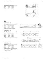
t Weight includes pendants and hardware. t Weight includes pins, basic frontstay & backstay pendants, and hardware. t Weights includes pins, pendants, and hardware. Number inside black circle V = # of components * — Optional equipment
Open the catalog to page 15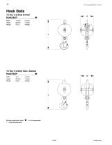
Hook Balls 15 Ton (13.6mt) Swivel Hook Ball*O Width 17.50 in (0.44m) 15 Ton (13.6mt) Non-Swivel Hook Ball*O Width 18 in (0.46m) Number inside black circle V = # of components * - Optional equipment
Open the catalog to page 16
Hook Blocks 50 Ton (45.4mt) 4-Sheave Hook Block* O Widthl 22.75 in (0.58m) Number inside black circle V = # of components * - Optional equipment Based on basic crane including Isuzu AH-6HK1X diesel engine, turntable bearing, live
Open the catalog to page 17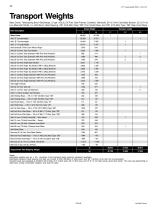
Transport Weights Base Crane: Telescoping Boom Backstops, 27 gal (102.2L) Of Fuel, Side Frames, Catwalks, Handrails, 20' (6.10m) Tube Base Section, 22' (6.71m) Live Mast with Bridle, 14-Part Boom Hoist Reeving, 700' (213.36m) Type “DB” Front Hoist Rope, and 700' (213.36m) Type “DB” Rear Hoist Rope. Item Description | Gross Weight Base Crane Add “A’ Counterweight Add “B” Counterweight Add “C” Counterweight Add Hydraulic Third Drum Without Rope Add 20' (6.10m) Tube Top Section Add 10' (3.05m) Tube Extension With Pins And Pendants Add 20' (6.10m) Tube Extension With Pins And Pendants Add 30'...
Open the catalog to page 18All Link-Belt catalogs and technical brochures
-
TCC-800
2 Pages
-
TCC-550
2 Pages
-
218|V
8 Pages
-
120|TT
2 Pages
-
CRANE GUIDE-2023
8 Pages
-
120|HT
32 Pages
-
65|HT
8 Pages
-
HTC-8640 SL
8 Pages
-
RTC-80160 SII
8 Pages
-
100|RT
8 Pages
-
85|RT
2 Pages
-
HTC8675 SERIES II
76 Pages
-
298 series2
8 Pages
-
HTT-8675 Series II
8 Pages
-
138 HSL
8 Pages
-
175|AT
4 Pages
-
120|RT
2 Pages
-
TCC-2500
8 Pages
-
TCC-1200
8 Pages
-
228 HSL
8 Pages
-
HTT-86110
12 Pages
-
110|RT
8 Pages
-
75|RT
2 Pages
-
RTC-80150
6 Pages
-
RTC-80130
6 Pages
-
RTC-8090 Series II
2 Pages
-
RTC-8080
2 Pages
-
RTC8065
2 Pages
-
TCC 500
2 Pages
-
TCC-750
2 Pages
-
238 HSL Series
6 Pages
-
298 Hylab HSL Series
6 Pages
-
ATC 3210
8 Pages
-
Link-Belt RTC-8050 Series II
2 Pages
-
Link-Belt RTC-8030 Series II
2 Pages
-
TCC-1100
6 Pages
-
298 HSL
6 Pages
-
238 HSL
2 Pages
-
218 HSL
6 Pages
-
108 HYLAB 5
6 Pages
-
ATC-3275
8 Pages
-
HTT-86100
6 Pages
-
HTC-3140
2 Pages
-
HTC-86100
2 Pages
-
HTC-8660 Series II
4 Pages
-
RTC-80130 Series II
2 Pages
-
RTC-80110 Series II
6 Pages
-
RTC-8065 Series II
2 Pages
-
Product Guide
8 Pages
Archived catalogs
-
Crane guide
8 Pages
-
Link-Belt RTC-8075
2 Pages


