- Catalogs
- Linearmech Srl
- LMR03 Catalog
LMR03 Catalog
1 /4Pages

LMR03 Catalog
1 /4Pages
Catalog excerpts

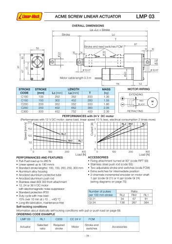
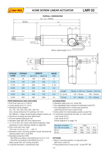
table.main {} tr.row {} td.cell {} div.block {} div.paragraph {} .font0 { font:5.00pt "Arial", sans-serif; } .font1 { font:8.00pt "Arial", sans-serif; } .font2 { font:9.00pt "Arial", sans-serif; } .font3 { font:11.00pt "Arial", sans-serif; } .font4 { font:13.00pt "Arial", sans-serif; } .font5 { font:15.00pt "Arial", sans-serif; } .font6 { font:18.00pt "Arial", sans-serif; } .font7 { font:21.00pt "Arial Black", sans-serif; } .font8 { font:26.00pt "Courier New", monospace; } .font9 { font:9.00pt "Lucida Sans Unicode", sans-serif; } .font10 { font:15.00pt "Trebuchet MS", sans-serif; } ACME SCREW LINEAR ACTUATOR LMR 03 OVERALL DIMENSIONS La = Lc + Stroke_ Stroke Lc T 10 50.5 F=L Motor cable length 0.3 m ,21.5, LTI CN (S T" J_ -1 _| : ------------- T l. J _ 19_ ,15 i ttt Ht TTT 12.5, er o c n e th 'I tor ot m 063 STROKE CODE STROKE [mm] LENGTH MASS [kg] Lc [mm] La [mm] C100 100 230 330 2.6 C150 150 280 430 2.9 C200 200 330 530 3.2 C250 250 380 630 3.5 C300 300 430 730 3.8 C400 400 580 980 4.7 C500 500 680 1180 5.3 056 Length Stroke 300 mm Stroke > 300 mm Lc [mm] 130 + Stroke 180 + Stroke T [mm] 113 + Stroke 163 + Stroke PERFORMANCES AND FEATURES ■ Pull-Push load up to 6 000 N ■ Linear speed up to 25 mm/s ■ Standard stroke lengths: 100, 150, 200, 250, 300, 400, 500 mm (min. stroke limited by FC switches: 50 mm) (for different / longer stroke lengths please contact us) ■ Aluminium housing and rear attachment ■ Chrome-plated steel push rod - tolerance f7 ■ Stainless steel AISI 303 front attachment ■ 1 2, 24 or 36 V DC motor with electromagnetic noise suppressor (motor features details on page 69) ■ Duty cycle with max. load: 15% over 10 min at (-10 ... +40) °C ■ Standard motor mounting position as per dimensional drawing (right-hand, code RH) ■ Standard protection IP65 - Test IP6X according to EN 60529 §12 §13.4-13.6 - Test IPX5 according to EN 60529 §14.2.5 (tests made with not running actuator) ■ Long-life lubrication, maintenance free ACCESSORIES ■ Stainless steel push rod (code SS) ■ Two adjustable built-in stroke end switches (code FC2) ■ Two adjustable built-in stroke end switches, switching off the motor (code FC2X) ■ Extra switch for intermediate position (code FC) ■ 2-channels incremental encoder on motor shaft 1 ppr (code GI 21) 4 ppr (code GI 24) (wiring diagrams on page 75) Number of pulses for 100 mm stroke Ratio RN2 RN1 RL2 RL1 GI 21 325 650 862 1 725 GI 24 1 300 2 600 3 450 6 900 OPTIONS ■ Motor mounting position on opposite side (left-hand, code LH) ■ Fixing attachment turned at 90° (code RPT 90) - 12 -
Open the catalog to page 1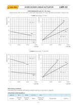
table.main {} tr.row {} td.cell {} div.block {} div.paragraph {} .font0 { font:4.00pt "Arial", sans-serif; } .font1 { font:6.00pt "Arial", sans-serif; } .font2 { font:8.00pt "Arial", sans-serif; } .font3 { font:9.00pt "Arial", sans-serif; } .font4 { font:11.00pt "Arial", sans-serif; } .font5 { font:13.00pt "Arial", sans-serif; } .font6 { font:18.00pt "Arial", sans-serif; } .font7 { font:20.00pt "Arial", sans-serif; } .font8 { font:15.00pt "Franklin Gothic Medium", sans-serif; } .font9 { font:17.00pt "Franklin Gothic Medium", sans-serif; } .font10 { font:16.00pt "Impact", sans-serif; } .font11...
Open the catalog to page 2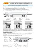
'Linear-Mech,j 13. STROKE END SWITCHES AND POSITIONING CONTROL 13.3 Electric stroke end switches FC (linear actuators LMR Sries) Each of the two micro-switches is fitted in a slot with a cam for switches commutation. A screw allows to lock the assembly in the desired position, adjusting in this way the switching position. The nut with suitable shape makes the cams rotate, so to activate the switches. This cam-operated device provides a stable and self-keeping commutation of the switches. The MIN. RETRACTED LENGTH Lc of the actuator is adjusted and controlled by switch FC1. The MAX. EXTENDED LENGTH...
Open the catalog to page 3
'Linear-Mech,j 13. STROKE END SWITCHES AND POSITIONING CONTROL 13.5 Encoder GI (linear actuators LMR 01, LMR02, LMR 03 and LMP03) Hall effect, bi-directional, incrmental encoder Output configuration: PUSH-PULL Code GI 21: 2 output channels, 1 pulse per revolution Code GI 24: 2 output channels, 4 pulses per revolution Cable length: as motor cable Protected against polarity inversion Protected against any incorrect output connection NOTE: For conductive cables colour, please refer to the wiring diagram in the "Installation Instructions" supplied with the product. Cl E O C N E GI 5 -f 24 Vdc 0 V...
Open the catalog to page 4All Linearmech Srl catalogs and technical brochures
 Ball Screw Jacks
128 Pages
 Linearmech - Catalogue 2012
81 Pages
 LME12 Catalog
2 Pages
 LME11 Catalog
2 Pages
 LME01 Catalog
1 Page
 MR40FC Catalog
2 Pages
 MR31 Catalog
2 Pages
 MR15 Catalog
2 Pages
 UBA0 Catalog
4 Pages
 CLB27 Catalog
3 Pages
 CLB25 Catalog
5 Pages
 BSA12 Catalog
3 Pages
 BSA11 Catalog
5 Pages
 BSA10 Catalog
6 Pages
 BSA08 Catalog
3 Pages
 UAL0 Catalog
4 Pages
 LMP03 Catalog
3 Pages
 LMI02 Catalog
2 Pages
 CLA28 - CLA28T Catalog
5 Pages
 CLA20 Catalog
3 Pages
 ATL12 Catalog
3 Pages
 ATL10 Catalog
6 Pages
 ATL08 Catalog
3 Pages
 ATL05 Catalog
3 Pages
 ATL02 Catalog
3 Pages
 LMR02 Catalog
4 Pages
 LMR01 Catalog
4 Pages


- Challenge Power Transmission cylinder
- Electric actuator
- Screw actuator
- Electric cylinder
- Motorized actuator
- Screw jack
- Ball screw actuator
- DC cylinder
- Ball screw jack
- Safety nut screw jack
- Motorized cylinder
- Cubic screw jack
- Trapezoidal screw actuator
- Nut screw jack
- Bevel gear screw jack
- Cylinder for photovoltaic applications
- Flange screw jack
- Compact screw jack