- Catalogs
- Linearmech Srl
- LMP03 Catalog
LMP03 Catalog
LMP03 Catalog
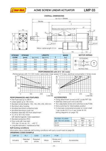
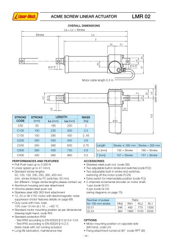
The document details the specifications of the LMP 03 linear actuator. It includes the number of pulses per 100 mm stroke for different ratios (RL2, RN1, RL1) and provides codes for incremental encoders (GI 21 and GI 24). Accessories such as fixing attachments, stainless steel push rods, and adjustable stroke end switches are listed.
Performance and Features:
The actuator supports a pull-push load up to 280 N and a linear speed up to 190 mm/s. It is available in standard stroke lengths of 100 to 300 mm and features an aluminum alloy housing with anodized protective components. The motor options include 12, 24, or 36 V DC with noise suppression, and the device has a standard protection rating of IP30. The duty cycle is 15% over 10 minutes at temperatures between -10 to +40°C, and it is maintenance-free due to long-life lubrication.
Stroke and Dimensions:
The document provides detailed stroke codes, lengths, and masses for different stroke lengths (100 mm to 300 mm). It also includes motor wiring instructions for extending and retracting operations.
Stroke End Switches and Positioning Control:
Magnetic and electric stroke end switches are described, including their configurations and wiring requirements. The magnetic reed switches (FCM) and electric switches (FCE) are adjustable and must be connected to a control circuit. The document warns against connecting these switches directly between the power supply and the motor.
Encoders:
The document describes the encoder options for the LMP 03 and other actuators. The GI encoder offers 1 or 4 pulses per revolution, while the EH38 encoder provides 100 pulses per revolution with a zero set pulse. Both encoders are protected against polarity inversion and incorrect connections.
General Notes:
Recommendations for connecting stroke end switches to PLC or PC systems are provided, emphasizing the need for galvanic separation circuits. The document also notes that safety clutches cannot be used with rotary encoders due to potential position reference loss.
Catalog excerpts

table.main {} tr.row {} td.cell {} div.block {} div.paragraph {} .font0 { font:5.00pt "Franklin Gothic Medium", sans-serif; } .font1 { font:7.00pt "Franklin Gothic Medium", sans-serif; } .font2 { font:10.00pt "Franklin Gothic Medium", sans-serif; } .font3 { font:12.00pt "Franklin Gothic Medium", sans-serif; } .font4 { font:15.00pt "Franklin Gothic Medium", sans-serif; } .font5 { font:16.00pt "Franklin Gothic Medium", sans-serif; } .font6 { font:18.00pt "Franklin Gothic Medium", sans-serif; } .font7 { font:22.00pt "Franklin Gothic Medium", sans-serif; } .font8 { font:34.00pt "Franklin Gothic Medium", sans-serif; } .font9 { font:19.00pt "Impact", sans-serif; } .font10 { font:55.00pt "Lucida Sans Unicode", sans-serif; } UaW-Mt.fACME SCREW LINEAR ACTUATOR LMP 03 OVERALL DIMENSIONS _La =Lc + Stroka Le Stroke end reed switches FCM Motor cable length 0.3 m STROKE CODE STROKE [mm] LENGTH MASS [kg] Le [mm] La mm) T C100 100 252 352 233 1.30 C150 150 302 452 283 1.55 C200 200 352 552 333 1.80 C250 250 402 652 383 2.05 C300 300 452 752 433 2.30 MOTOR WIRING EXTENCXNG RETRACTING PERFORMANCES with 24 V DC motor [Performances wrth 12 V DC motor: same foad, linear speed 10 % less, electrical con su motion 2 times more) |200 E 150 J J T n HUZ A ■ = m RN1 | flLI HN1 |RL1 100 T. 50 0 200 300 Load PERFORMANCES AND FEATURES PuH-Push bad up to 280 N Linear speed up to 190 mm/s « Standard stroke lengths: 100,150, 200,250,300 mm ■ Aluminium atoy housmg ■ Anodized aluminium protective tube ■ Anodized aluminium push rod - Stainfess steel AJSI303 front attachment 0 'ZO 200 300 Load IN] ACCESSORIES Օ FiWng attachment turned at 90° (code RPT 90) Stainless steel push rod (code SS) ■ Two adjustable stroke end switches (code FCM) Օ Extra switches for intermediate position ■ 2-channels incrmental encoder on motor shaft 1 ppr (code Gl 21) or 4 ppr (code Gl 24) (wiring diagrams on page 75) ■ 12,24 or 36 VDC motor with electromagnetic noise suppressor - Standard protection IP30 ■ Duty cycle wrth max bad: 15% over 10 mh at (-10... +40) °C ■ Long-life lubrication, maintenance free Number of puises per 100 mm stroke Ratio RL2 RN1 RL1 Gl 21 34 67 91 Gl 24 136 267 364 SelMocking conditions Information about staticaty sell-locking conditions with pull or push load on page 68. 0RDERING CODE EXAMPLE LMP 03 RL1 C200 CC 24 V FCM Actuator Select ed ratio Requirad stroke Motor Stroke end switches Accessones 39-
Open the catalog to page 1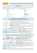
IȊF4ʈK.J 13. STROKE END SWITCHES AND POSITIONING CONTROL GENERAL NOTE In case the linear actuator is used in an application where the stroke end switches must be connected to PLC or PC, we suggest to make the connection with a galvanic sȩparation circuit. 24 V DC t- 24VDC- O _ I PLC/PC PLC/PC 13.1 Magnetic stroke end switches (reed) FCM [linear actuators ATL BSA, UAL, UBA Sries, LMI 02 and LMP 03) The magnetic fieW of the ring fixed on the nut activtes the reed contact ol the switch locked on the protective tube with a clamp. The position of the switches along the tube is easily adjustable. The...
Open the catalog to page 2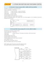
UaW-Mt.f 13. STROKE END SWITCHES AND POSITIONING CONTROL _13.5 Encoder Gl (linear actuators LMR 01, LMR02, LMR 03 and LMP03)_ Hall effect. bi-directional, incrmental encoder Output configuration: PUSH-PULL Code Gl 21: 2 output channels. 1 puise per r⩩volution Code Gl 24: 2 output channels. 4 puises per rvolution Cable length: as motor cable Protected against polarity inversion Protected against any incorrect output connection NOTE: For conductive cables colour, please refer to the wiring diagram in the "Installation Instructions supplied with the product. 5 -r 24 Vdc OV POWER SUPPLY ChannelAn_n_...
Open the catalog to page 3All Linearmech Srl catalogs and technical brochures
 Ball Screw Jacks
128 Pages
 Linearmech - Catalogue 2012
81 Pages
 LME12 Catalog
2 Pages
 LME11 Catalog
2 Pages
 LME01 Catalog
1 Page
 MR40FC Catalog
2 Pages
 MR31 Catalog
2 Pages
 MR15 Catalog
2 Pages
 UBA0 Catalog
4 Pages
 CLB27 Catalog
3 Pages
 CLB25 Catalog
5 Pages
 BSA12 Catalog
3 Pages
 BSA11 Catalog
5 Pages
 BSA10 Catalog
6 Pages
 BSA08 Catalog
3 Pages
 UAL0 Catalog
4 Pages
 LMI02 Catalog
2 Pages
 CLA28 - CLA28T Catalog
5 Pages
 CLA20 Catalog
3 Pages
 ATL12 Catalog
3 Pages
 ATL10 Catalog
6 Pages
 ATL08 Catalog
3 Pages
 ATL05 Catalog
3 Pages
 ATL02 Catalog
3 Pages
 LMR03 Catalog
4 Pages
 LMR02 Catalog
4 Pages
 LMR01 Catalog
4 Pages


- Cylinder
- Electric actuator
- Screw actuator
- Electric cylinder
- Motorized actuator
- Screw jack
- Ball screw actuator
- DC cylinder
- Ball screw jack
- Safety nut screw jack
- Motorized cylinder
- Cubic screw jack
- Trapezoidal screw actuator
- Nut screw jack
- Bevel gear screw jack
- Cylinder for photovoltaic applications
- Flange screw jack
- Compact screw jack