
- Catalogs
- Linearmech Srl
- CLB25 Catalog

CLB25 Catalog

CLB25 Catalog
The document provides detailed specifications for the Ball Screw Linear Actuator CLB 25 with both AC and DC motor options. The overall dimensions are defined by the actuator's length (Lc) and the stroke length, with specific measurements provided for different stroke codes ranging from 100 mm to 400 mm. The actuator's mass varies slightly depending on the attachment type and stroke length.
Performance and Features
The actuators are capable of handling push loads up to 5,000 N and pull loads up to 4,000 N, with linear speeds reaching up to 125 mm/s. Standard stroke lengths are available in increments of 50 mm from 100 mm to 400 mm. The actuators feature a ball screw design (BS 14 x 5 or BS 14 x 10) and are housed in anodized aluminum with a chrome-plated steel push rod. They are equipped with a rear attachment made of zinc-plated steel or aluminum alloy, and a standard head or rod end in stainless steel.
Motor and Electrical Specifications
The AC motor operates on a 3-phase 50 Hz 230/400 V or 1-phase 50 Hz 230 V supply, while the DC motor options include 12 or 24 V. The duty cycle allows for 100% operation over 10 minutes within a temperature range of -10 to +40 °C. The standard protection rating is IP 55 for AC motors and IP 54 for DC motors.
Accessories and Options
Various accessories are available, including different front attachments, stainless steel push rods, rear brackets, and mechanical overload protection. Adjustable electric stroke end switches and rotative potentiometers for positioning control are also offered. Options include motor mounting on the opposite side and fixing attachments turned at 90 degrees.
Ordering and Self-Locking Conditions
The document provides an example of an ordering code, detailing the selection of actuator type, ratio, stroke, motor, stroke end switches, accessories, and options. Self-locking conditions are achievable with a brake motor only, with further details provided on page 68.
Stroke End Switches and Positioning Control
The document describes the use of electric cam-operated stroke end switches and rotative potentiometers for positioning control. The switches can be configured for different contact types, and the potentiometer provides an analog output signal proportional to the actuator's position.
Catalog excerpts
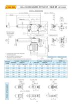
table.main {} tr.row {} td.cell {} div.block {} div.paragraph {} .font0 { font:4.00pt "Arial", sans-serif; } .font1 { font:6.00pt "Arial", sans-serif; } .font2 { font:7.00pt "Arial", sans-serif; } .font3 { font:8.00pt "Arial", sans-serif; } .font4 { font:9.00pt "Arial", sans-serif; } .font5 { font:10.00pt "Arial", sans-serif; } .font6 { font:11.00pt "Arial", sans-serif; } .font7 { font:13.00pt "Arial", sans-serif; } .font8 { font:17.00pt "Arial", sans-serif; } .font9 { font:18.00pt "Arial", sans-serif; } .font10 { font:36.00pt "Courier New", monospace; } .font11 { font:7.00pt "Microsoft Sans Serif", sans-serif; } .font12 { font:34.00pt "Microsoft Sans Serif", sans-serif; } BALL SCREW LINEAR ACTUATOR CLB 25 AC motor OVERALL DIMENSIONS La =Lc + Stroke La = Lc + Stroke Stroke Lc Capacitor 45.5 91.5 98 Rear bracket SP Pin 01Oh7 a- ■+ 01OH7 Standard head with threaded hollow bore BA tNE h e 1. STROKE END SWITCHES BOX AND POTENTIOMETER 2. MOTOR SHAFT EXTENSION for: Emergency manual activation Stroke end switches and potentiometer adjustment -1 Attachment A1 "1/ ^ 111 Q [mm] Attachment A1 Attachment A2 253 260 STROKE CODE Actuator - Attachment A1 Actuator - Attachment A2 MASS [Kg] STROKE [mm] LENGTH T [mm] STROKE [mm] LENGTH T [mm] standard motor brake motor Lc [mm] La [mm] Lc [mm] La [mm] C100 100 348 448 317 100 355 455 324 5.2 5.7 C150 150 398 548 367 150 405 555 374 5.3 5.8 C200 200 448 648 417 200 455 655 424 5.5 6.0 C250 250 498 748 467 250 505 755 474 5.6 6.1 C300 300 548 848 517 300 555 855 524 5.8 6.3 C400 400 648 1048 617 400 667 1067 624 6.1 6.6 ROD END CLEVIS END BALL JOINT ROE 01OF7 FO TS 01OH8 01OH7 I f > h 49 Lc = Q + Stroke Z O LL TCL 15 12 20 45 - 54 -
Open the catalog to page 1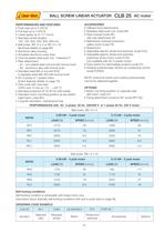
'Linear-Mech,j BALL SCREW LINEAR ACTUATOR CLB 25 AC motor PERFORMANCES AND FEATURES ■ Push load up to 5 000 N ■ Pull load up to 4 000 N ■ Linear speed up to 117 mm/s ■ Standard stroke lengths: 100, 150, 200, 250, 300, 400 mm ■ Ball screw BS 14 x 5 or BS 14 x 10 (technical details on page 66) ■ Aluminium alloy housing ■ Anodized aluminium outer tube ■ Chrome-plated steel push rod - tolerance f7 ■ Rear attachment: - A1: zinc-plated steel rod end with bronze bush - A2: aluminium alloy with bronze bush ■ Standard head BA or rod end ROE in stainless steel AISI 303 with bronze bush ■ AC 3-phase or...
Open the catalog to page 2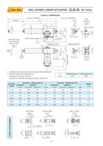
table.main {} tr.row {} td.cell {} div.block {} div.paragraph {} .font0 { font:4.00pt "Arial", sans-serif; } .font1 { font:6.00pt "Arial", sans-serif; } .font2 { font:7.00pt "Arial", sans-serif; } .font3 { font:8.00pt "Arial", sans-serif; } .font4 { font:9.00pt "Arial", sans-serif; } .font5 { font:10.00pt "Arial", sans-serif; } .font6 { font:13.00pt "Arial", sans-serif; } .font7 { font:17.00pt "Arial", sans-serif; } .font8 { font:21.00pt "Arial", sans-serif; } .font9 { font:4.00pt "Franklin Gothic Medium", sans-serif; } .font10 { font:7.00pt "Microsoft Sans Serif", sans-serif; } .font11 { font:15.00pt...
Open the catalog to page 3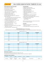
'Linear-Mech,j BALL SCREW LINEAR ACTUATOR CLB 25 DC motor PERFORMANCES AND FEATURES ■ Push load up to 5 000 N ■ Pull load up to 4 000 N ■ Linear speed up to 125 mm/s ■ Standard stroke lengths: 100, 150, 200, 250, 300, 400 mm ■ Ball screw BS 14 x 5 or BS 14 x 10 (technical details on page 66) ■ Aluminium alloy housing ■ Anodized aluminium outer tube ■ Chrome-plated steel push rod - tolerance f7 ■ Rear attachment: - A1: zinc-plated steel rod end with bronze bush - A2: aluminium alloy with bronze bush ■ Standard head BA or rod end ROE in stainless steel AISI 303 with bronze bush ■ 1 2 or 24 V DC...
Open the catalog to page 4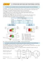
13. STROKE END SWITCHES AND POSITIONING CONTROL 13.4 Electric cam-operated stroke end switches (linear actuators CLA and CLB Series) Code FC2: two electric cam-operated switches, wired on contact NC (to be connected into the exter-nal control circuit). On request, the switches can be wired on the contact NO or on the switch-over contact CS. (For available configurations please contact our Technical Dpt). Code FC2X: two electric cam-operated switches, internally wired between power supply and electric motor, in order to switch off the power supply directly, without relays. Available for actuators...
Open the catalog to page 5All Linearmech Srl catalogs and technical brochures
 Ball Screw Jacks
128 Pages
 Linearmech - Catalogue 2012
81 Pages
 LME12 Catalog
2 Pages
 LME11 Catalog
2 Pages
 LME01 Catalog
1 Page
 MR40FC Catalog
2 Pages
 MR31 Catalog
2 Pages
 MR15 Catalog
2 Pages
 UBA0 Catalog
4 Pages
 CLB27 Catalog
3 Pages
 BSA12 Catalog
3 Pages
 BSA11 Catalog
5 Pages
 BSA10 Catalog
6 Pages
 BSA08 Catalog
3 Pages
 UAL0 Catalog
4 Pages
 LMP03 Catalog
3 Pages
 LMI02 Catalog
2 Pages
 CLA28 - CLA28T Catalog
5 Pages
 CLA20 Catalog
3 Pages
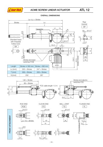 ATL12 Catalog
3 Pages
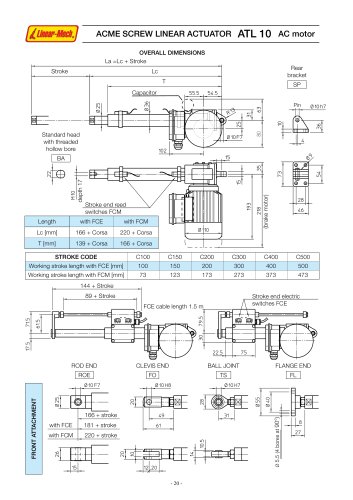 ATL10 Catalog
6 Pages
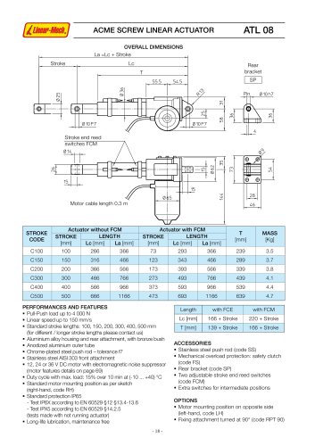 ATL08 Catalog
3 Pages
 ATL05 Catalog
3 Pages
 ATL02 Catalog
3 Pages
 LMR03 Catalog
4 Pages
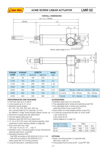 LMR02 Catalog
4 Pages
 LMR01 Catalog
4 Pages


- Cylinder
- Electric actuator
- Screw actuator
- Electric cylinder
- Ball screw actuator
- Screw jack
- Motorized actuator
- DC cylinder
- Ball screw jack
- Safety nut screw jack
- Motorized cylinder
- Cubic screw jack
- Trapezoidal screw actuator
- Nut screw jack
- Bevel gear screw jack
- Flange screw jack
- Cylinder for photovoltaic applications
- Compact screw jack