- Catalogs
- Linearmech Srl
- Ball Screw Jacks
Ball Screw Jacks
1 /128Pages

Ball Screw Jacks
1 /128Pages
Catalog excerpts

Ball Screw Jacks
Open the catalog to page 1
© Copyright SERVOMECH This catalogue contents are under publisher copyright and may not be reproduced unless permission is agreed. Every care has been taken to ensure the accuracy of the information contained in this catalogue, but no liability can be accepted for any errors or omissions.
Open the catalog to page 2
page page page page page page page page page page page 2. Ball screw jacks with travelling screw (Mod.A)
Open the catalog to page 3
Ball screw jacks 3. Ball screw jacks with travelling nut (Mod.B) page 62 page 63 page 64 page 65 page 65 page 66 page 68 page 70 page 72 page 72 page 73 page 74 page 75 page 76 page 77 page 78 page 79 page 80 page 80 page 81 page 82 page 82 page 84 page 86 page 88 page 90 page 91 page 96 page 96 page 98 page 100 page 102 page 105 page 106 page 108 page 110 page 112 5. LINEARMECH Brushless Servomotors page 115 page 116 page 117 page 118
Open the catalog to page 4
Ball screw jacks 1.1 Ball screw jacks description Screw jacks transform a rotary motion of an electric, hydraulic or pneumatic motor or even a manual operation into a vertical linear lifting motion (push or pull) or into a horizontal positioning motion. Screw jacks can be installed as a single unit or in lifting systems with different layouts connected by transmission shafts, couplings and bevel gearboxes. Screw jacks enable the synchronized constant movement of lifting systems even with a not uniformly distributed load. Ball screw jacks combine the gear unit with a linear drive performed by...
Open the catalog to page 5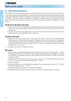
Ball screw jacks 1.2 Manufacturing features SERVOMECH screw jacks are designed and manufactured using high technology and CNC machine tools. All working processes inside SERVOMECH comply to its Quality Management System, developed according to ISO 9001:2008 and certified by TÜV Italia. Check tests are carried out in-line during all manufacturing processes to monitor and adjust possible errors, obtaining a constant quality of the production without reject. Final control and functional checks are carried out to ensure high quality and reliability of the final product. MA BS and SJ BS Series screw...
Open the catalog to page 6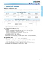
Ball screw jacks 1.3 Materials and Components Ball screws used in screw jacks • Threaded shafts: quenched and tempered alloy steel 42 CrMo 4 or 50 CrMo 4 (UNI EN 10083) Threaded bars available on stock (nominal diameter × nominal lead, in mm): ROLLED, accuracy grade IT 7 BS 16×5 MACHINED, accuracy grade IT 5 (IT 3) BS 16×5 • Nuts: case-hardened alloy steel 18 NiCrMo 5 (UNI EN 10084) MA Series and SJ Series screw jacks • Housing: casting in hardened and tempered aluminium alloy EN 1706 - AC-AlSi10Mg T6 casting in grey cast iron EN-GJL-250 (UNI EN 1561) casting in spheroidal graphite iron EN-GJS-500-7...
Open the catalog to page 7
Ball screw jacks 1.4 Ball screw jacks overview Ball screw jacks high efficiency screw jacks, suitable for continuous operation, duty cycle up to 100 %, ratio from 1 : 4 to 1 : 32, input speed up to 3 000 rpm standard performances screw jacks, available only in Mod. B - travelling nut, duty cycle up to 70 %, ratio from 1 : 4 to 1 : 36, input speed up to 1 500 rpm high speed screw jacks, available only in Mod. B - travelling nut, suitable for continuous operation, duty cycle up to 100 %, ratio from 1 : 1 to 1 : 4, input speed up to 3 000 rpm 8 standard sizes with load capacity from 5 kN to 350...
Open the catalog to page 8
Ball screw jacks 1.5 Models Ball screw jacks are available in two different models: • travelling screw (Model A) • travelling nut (Model B) Model A - travelling screw The ball nut is integral with the worm wheel. The linear motion is performed by the ball screw being driven by the nut through the screw jack housing, therefore there must be enough space on both screw jack sides. In operation, the screw does not rotate and its translation is possible only if the reacting torque is applied. Accessories: • protective tube • protective bellows • safety nut • various screw end attachments • limit switches...
Open the catalog to page 9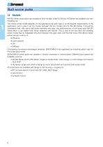
Ball screw jacks 1.5 Models MA BS Series screw jacks are available in both models, while SJ BS and HS Series are available only with travelling nut. The choice of the model depends on the selected screw jack type or on the specific requirements of the application, but in case it can be chosen between the two models (only for MA BS Series), it should be considered that, with same ball screw diameter and lead, the performances of the screw jack MA BS Series Mod. A are higher than those obtained with Mod.B. This is due to the fact that the travelling screw model has an integrated structure between...
Open the catalog to page 10
Ball screw jacks 1.6 Design – screw jacks MA BS Series and SJ BS Series INPUT SHAFT ROTATION – SCREW OR NUT LIFTING DIRECTION • Vers.1: single input shaft • Vers.2: double input shaft • Vers.3: flange and hollow shaft for IEC/servo motor • Vers.4: flange and hollow shaft for IEC/servo motor + second input shaft • Vers.5: Vers.1 + bell housing and coupling for IEC/servo motor • Vers.6: Vers.2 + bell housing and coupling for IEC/servo motor SCREW JACK MOUNTING POSITIONS UPWARD (U)
Open the catalog to page 11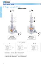
Ball screw jacks 1.7 Design – screw jacks HS Series KINEMATICS SCHEME Scheme 10 Bevel gear wheel on side opposite to nut Scheme 20 Bevel gear wheel on nut side • Designation S: solid shaft with key, standard diameter • Designation R: solid shaft with key, larger diameter • Designation MF: flange and hollow shaft for IEC/servo motor • Designation MA: special flange for servo or hydraulic motor
Open the catalog to page 12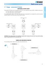
Ball screw jacks 1.7 Design – screw jacks HS Series ADDITIONAL OUTPUT SHAFT Screw jacks HS Series can be equipped with one or more additional output shafts. Available versions are: • S: solid shaft with key, standard diameter • R: solid shaft with key, larger diameter The shafts position refers to the main input shaft and is expressed by an angle with counter-clockwise positive direction and screw jack top view (ball nut side). additional output shaft 180° additional output shaft 270° additional output shaft 90° WARNING! The rotating speed of the additional output shaft is always the same as...
Open the catalog to page 13All Linearmech Srl catalogs and technical brochures
 Linearmech - Catalogue 2012
81 Pages
 LME12 Catalog
2 Pages
 LME11 Catalog
2 Pages
 LME01 Catalog
1 Page
 MR40FC Catalog
2 Pages
 MR31 Catalog
2 Pages
 MR15 Catalog
2 Pages
 UBA0 Catalog
4 Pages
 CLB27 Catalog
3 Pages
 CLB25 Catalog
5 Pages
 BSA12 Catalog
3 Pages
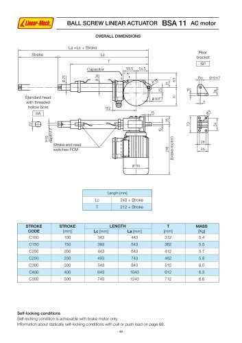 BSA11 Catalog
5 Pages
 BSA10 Catalog
6 Pages
 BSA08 Catalog
3 Pages
 UAL0 Catalog
4 Pages
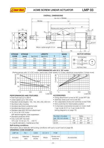 LMP03 Catalog
3 Pages
 LMI02 Catalog
2 Pages
 CLA28 - CLA28T Catalog
5 Pages
 CLA20 Catalog
3 Pages
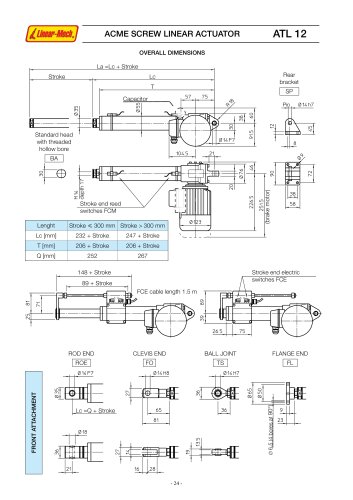 ATL12 Catalog
3 Pages
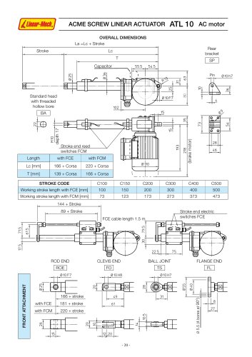 ATL10 Catalog
6 Pages
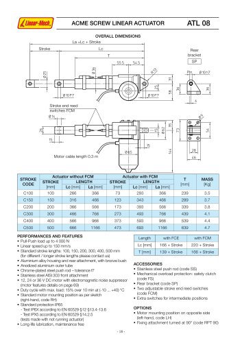 ATL08 Catalog
3 Pages
 ATL05 Catalog
3 Pages
 ATL02 Catalog
3 Pages
 LMR03 Catalog
4 Pages
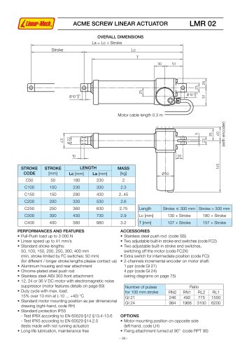 LMR02 Catalog
4 Pages
 LMR01 Catalog
4 Pages


- Cylinder
- Actuator
- Linear actuator
- Electric actuator
- Screw actuator
- Electric cylinder
- Motorized actuator
- Ball screw actuator
- DC cylinder
- Safety nut screw jack
- Motorized cylinder
- Cubic screw jack
- Trapezoidal screw actuator
- Nut screw jack
- Bevel gear screw jack
- Cylinder for photovoltaic applications
- Flange screw jack
- Compact screw jack