
- Catalogs
- Linearmech Srl
- ATL10 Catalog

ATL10 Catalog
ATL10 Catalog
The document details the specifications of the ACME Screw Linear Actuator ATL 10, which includes both AC and DC motor options. The actuator can handle push loads up to 5,000 N and pull loads up to 4,000 N, with linear speeds reaching up to 150 mm/s. Standard stroke lengths are available in increments from 100 mm to 500 mm, with custom lengths available upon request. The actuator features an aluminum alloy housing, anodized aluminum outer tube, and a chrome-plated steel push rod.
Procedures and Standards:
The actuator is designed for a duty cycle of 30% over 10 minutes at temperatures ranging from -10 to +40°C. It comes with a standard protection rating of IP55, or IP54 with a brake. The motor can be mounted in a right-hand position by default, with an option for left-hand mounting. The actuator is maintenance-free due to its long-life lubrication.
Performance and Features:
The actuator is available with different screw configurations (1-start, 2-starts, and 3-starts) that affect load capacity and speed. The AC motor options include 0.09 kW and 0.12 kW motors, while the DC motor operates at 12 or 24 V. The document provides detailed performance metrics for each configuration, including load, speed, and current requirements.
Accessories and Options:
Available accessories include different front attachments, stainless steel push rods, rear brackets, mechanical overload protection, and brake motors. Stroke end switches (reed and electric) are available for position control, with options for intermediate position switches and electromechanical switches for speeds up to 30 mm/s. Additional options include motor mounting on the opposite side and fixing attachments turned at 90 degrees.
Recommendations:
For applications requiring connection to PLC or PC, it is recommended to use a galvanic separation circuit. The document warns against connecting magnetic reed switches directly between the power supply and the electric motor.
Ordering Information:
The document provides examples of ordering codes, detailing how to specify the actuator, selected ratio, required stroke, motor type, stroke end switches, and any additional accessories or options.
Catalog excerpts
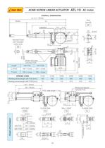
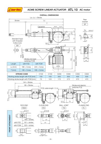
table.main {} tr.row {} td.cell {} div.block {} div.paragraph {} .font0 { font:5.00pt "Arial", sans-serif; } .font1 { font:6.00pt "Arial", sans-serif; } .font2 { font:7.00pt "Arial", sans-serif; } .font3 { font:8.00pt "Arial", sans-serif; } .font4 { font:9.00pt "Arial", sans-serif; } .font5 { font:10.00pt "Arial", sans-serif; } .font6 { font:13.00pt "Arial", sans-serif; } .font7 { font:18.00pt "Arial", sans-serif; } .font8 { font:34.00pt "Arial", sans-serif; } .font9 { font:7.00pt "Lucida Sans Unicode", sans-serif; } .font10 { font:14.00pt "Microsoft Sans Serif", sans-serif; } .font11 { font:9.00pt "Times New Roman", serif; } ACME SCREW LINEAR ACTUATOR ATL 10 AC motor OVERALL DIMENSIONS La =Lc + Stroke Stroke Rear bracket I SP I Pin 01Oh7 Standard head with threaded hollow bore &\-r \ ~°\ 1 i|n 1 4 J>i. BA ce Length with FCE with FCM Lc [mm] 166 + Corsa 220 + Corsa T [mm] 139 + Corsa 166 + Corsa tor ot m e k ra i5 28 46 STROKE CODE C100 C150 C200 C300 C400 C500 Working stroke length with FCE [mm] 100 150 200 300 400 500 Working stroke length with FCM [mm] 73 123 173 273 373 473 , 144 + Stroke , 89 + Stroke FCE cable length 1.5 m Stroke end electric switches FCE m--------q-^-g Vf J 3B -/-A- -f---T- ml m r: 3 C ---- 1[ ח -> C 1- 22.5 75 -----a ROD END CLEVIS END BALL JOINT FLANGE END ROE FO TS FL 01OF7 01OH8 01OH7 o Vf S - - 166 + stroke rai M- 49 31 with FCE 181 + stroke 61 0 9 cp o 27 A T N O R LL with FCM 220 + stroke 10.5 -, -fn I_ CN חh I 4--■ . o O" CN 15 12 ,20 LO LO S - 20 -
Open the catalog to page 1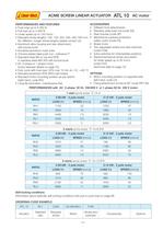
'Linear-Mech,j ACME SCREW LINEAR ACTUATOR ATL 10 AC motor PERFORMANCES AND FEATURES ■ Push load up to 5 000 N ■ Pull load up to 4 000 N ■ Linear speed up to 140 mm/s ■ Standard stroke lengths: 100, 150, 200, 300, 400, 500 mm (for different / longer stroke lengths please contact us) ■ Aluminium alloy housing and rear attachment, with bronze bush ■ Anodized aluminium outer tube ■ Chrome-plated steel push rod - tolerance f7 ■ Standard head BA or rod end ROE in stainless steel AISI 303 with bronze bush ■ AC 3-phase or 1-phase motor (motor features details on page 70) ■ Duty cycle with max load: 30%...
Open the catalog to page 2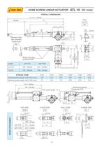
table.main {} tr.row {} td.cell {} div.block {} div.paragraph {} .font0 { font:8.00pt "Arial", sans-serif; } .font1 { font:9.00pt "Arial", sans-serif; } .font2 { font:10.00pt "Arial", sans-serif; } .font3 { font:13.00pt "Arial", sans-serif; } .font4 { font:18.00pt "Arial", sans-serif; } .font5 { font:24.00pt "Arial", sans-serif; } .font6 { font:34.00pt "Arial", sans-serif; } .font7 { font:12.00pt "Impact", sans-serif; } .font8 { font:7.00pt "Lucida Sans Unicode", sans-serif; } .font9 { font:8.00pt "Tahoma", sans-serif; } .font10 { font:9.00pt "Times New Roman", serif; } ACME SCREW LINEAR ACTUATOR...
Open the catalog to page 3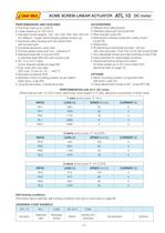
'Linear-Mech,j ACME SCREW LINEAR ACTUATOR ATL 10 DC motor PERFORMANCES AND FEATURES ■ Pull-Push load up to 4 000 N ■ Linear speed up to 150 mm/s ■ Standard stroke lengths: 100, 150, 200, 300, 400, 500 mm (for different / longer stroke lengths please contact us) ■ Aluminium alloy housing and rear attachment, with bronze bush ■ Anodized aluminium outer tube ■ Chrome-plated steel push rod - tolerance f7 ■ Standard head BA or rod end ROE in stainless steel AISI 303 with bronze bush ■ DC 12 or 24 V motor (motor features details on page 69) ■ Duty cycle with max load: 30% over 10 min at (-10 ... +40)...
Open the catalog to page 4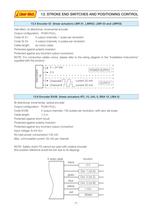
'Linear-Mech,j 13. STROKE END SWITCHES AND POSITIONING CONTROL 13.5 Encoder GI (linear actuators LMR 01, LMR02, LMR 03 and LMP03) Hall effect, bi-directional, incrmental encoder Output configuration: PUSH-PULL Code GI 21: 2 output channels, 1 pulse per revolution Code GI 24: 2 output channels, 4 pulses per revolution Cable length: as motor cable Protected against polarity inversion Protected against any incorrect output connection NOTE: For conductive cables colour, please refer to the wiring diagram in the "Installation Instructions" supplied with the product. ce E O C N E GI 5 + 24 Vdc 0 V...
Open the catalog to page 6All Linearmech Srl catalogs and technical brochures
 Ball Screw Jacks
128 Pages
 Linearmech - Catalogue 2012
81 Pages
 LME12 Catalog
2 Pages
 LME11 Catalog
2 Pages
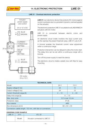 LME01 Catalog
1 Page
 MR40FC Catalog
2 Pages
 MR31 Catalog
2 Pages
 MR15 Catalog
2 Pages
 UBA0 Catalog
4 Pages
 CLB27 Catalog
3 Pages
 CLB25 Catalog
5 Pages
 BSA12 Catalog
3 Pages
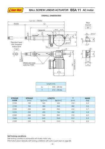 BSA11 Catalog
5 Pages
 BSA10 Catalog
6 Pages
 BSA08 Catalog
3 Pages
 UAL0 Catalog
4 Pages
 LMP03 Catalog
3 Pages
 LMI02 Catalog
2 Pages
 CLA28 - CLA28T Catalog
5 Pages
 CLA20 Catalog
3 Pages
 ATL12 Catalog
3 Pages
 ATL08 Catalog
3 Pages
 ATL05 Catalog
3 Pages
 ATL02 Catalog
3 Pages
 LMR03 Catalog
4 Pages
 LMR02 Catalog
4 Pages
 LMR01 Catalog
4 Pages


- Cylinder
- Electric actuator
- Screw actuator
- Electric cylinder
- Ball screw actuator
- Screw jack
- Motorized actuator
- DC cylinder
- Ball screw jack
- Safety nut screw jack
- Motorized cylinder
- Cubic screw jack
- Trapezoidal screw actuator
- Nut screw jack
- Bevel gear screw jack
- Flange screw jack
- Cylinder for photovoltaic applications
- Compact screw jack