AIRY
1 /6Pages

AIRY
1 /6Pages
Catalog excerpts
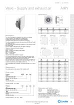
AIRYFP ELLI Description The valve is designed for installation at a wall or in a ceiling. It can be used for new-build and for replacement. Its smart grip function ensures an easy installation. Its unique sound data ensure an optimum sound level. The valve consists of two parts; the valve body (AIRYB) and the flat front plate (AIRYFP). The valve body is fixed to the duct system or a valve socket via flexible spring wings. The front plate is attached to the valve body via springs. There are 5 standard front plate shapes: ROUN - a circle, BOW - a square with sligthly bulged edges, SQUA - a square, ELLI - an super ellipse. RECT - a rectangle, Special shapes are possible on request. It is recommended that the valve is mounted in the frame ILVRU. The product will also fit in the valve frames VRGU, VRGM, VRFU, VRFM and the products BU GJUT, and TCPU GJUT. The valve body has to cover the brim of the product it is fitted into. Therefor the maximum diameter of the brim for 0100 is 133,5 mm, for 0125 is 152,5 mm and for 0160 is 187,5 mm. Can be equipped with a blanking - off sector plate for 2 or 3 way air flow. Maintenance The visible parts can be wiped off with a damp cloth. Order code AIRYB Connection dim. 0d 0d nom = 100, 125, 160 mm Colour RAL 9003, RAL 9010 100 Connection dim. 0d 0d nom = 100, 125, 160 mm Type BOW, ELLI, RECT, ROUN, SQUA Colour RAL 9003, RAL 9010 Example: AIRYFP - 125 - ELLI - 9003 Material: Galvanized sheet metal. Colour: White RAL 9003, gloss 30 or white RAL 9010, gloss 30. Special colours are available on request. The front plate can be ordered in stainless steel. It is also possible to paint the front plate with standard wall paint or to cover it with wallpaper. We reserve the right to make changes without prior notice 2015-03-18
Open the catalog to page 1
Valve - Supply and exhaust air AIRY Technical data Capacity Air flow qv [l/s] and [m3/h], total pressure Apt [Pa], throw l0.2 [m] and sound power level LWA [dB(A)] can be seen in the graphs. Frequency-related sound power level The sound power level in the frequency band is defined as LWA+Kok. Kok values are specified in charts beneath the graphs on the following pages. Sound attenuation Sound attenuation of the diffusers AL from duct to room, including end reflection, see table below. Balancing Balancing data is contained in a separate brochure. Blanking off sector plate Correction for sound...
Open the catalog to page 2
Valve – Supply and exhaust air Technical data Throw l0.2 Throw l0.2 [m] can be seen in the graphs for isothermal air, at a terminal velocity of 0,2 m/s. l0.2 [m] 5 We reserve the right to make changes without prior notice 2015-03-18
Open the catalog to page 3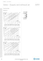
We reserve the right to make changes without prior notice 2015-03-18
Open the catalog to page 4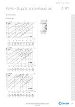
We reserve the right to make changes without prior notice 2015-03-18
Open the catalog to page 5
Valve - Supply and exhaust air Airy with bend and T-piece Sound correction values: Add this value to the diagram for Airy when using T-piece or bend. We reserve the right to make changes without prior notice 2015-03-18
Open the catalog to page 6All LINDAB catalogs and technical brochures
 Lindab UltraLink®
12 Pages
 Professor XP
7 Pages
 DCV ONE
4 Pages
 Lindab System Solutions
20 Pages
 Lindab Facade Cassettes
12 Pages
 LindabRubigo
4 Pages
 LindabMagestic
4 Pages
 LindabDuraFrost
4 Pages
 Standing seam roofing
16 Pages
 KIR
KIR3 Pages
 KI
KI3 Pages
 KDPF
KDPF2 Pages
 FDV
FDV2 Pages
 Cleanroom diffusers
20 Pages
 Plenum boxes
8 Pages
 Fresh air overflow
14 Pages
 Air flow regulators
14 Pages
 Ventilation Product Range
8 Pages
 Short reducer
4 Pages
 Stainless Duct Systems?
2 Pages
 Purlins
8 Pages
 Exteroir wall profiles
14 Pages
 Industrial doors
12 Pages
 Garage doors
12 Pages
 Flashings
8 Pages
 Sandwich panels
10 Pages
 Rainwater systems
18 Pages
 ROCA
ROCA12 Pages
 Profiled sheeting
14 Pages
 SRP 25
8 Pages
 Grilles
46 Pages
 Wall diffusers
44 Pages
 VAV
VAV65 Pages
 Air Duct Systems - Schalldämpfer
69 Pages


Archived catalogs
 Partition wall profiles
12 Pages
 Facade cassettes
8 Pages
 Battens
8 Pages
 Roof safety system
8 Pages
 Tile effect roofing
14 Pages
 Lindab Roof Drainage System
16 Pages
 Acoustic solutions
6 Pages
 LindabSRP25
8 Pages
 Astron Corporate Brochure
12 Pages
 Astron MBS Brochure 2008
12 Pages
 Astron SSB Brochure 2008
12 Pages
- Piping
- Lumibird fitting
- Lumibird manual valve
- Lumibird hydraulic fitting
- Metal fitting
- Lumibird measuring instrument
- Quick coupling
- Semi-rigid tube
- Lumibird gate valve
- Protection sleeve
- Lumibird steel valve
- Lumibird air valve
- Plastic valve
- Lumibird leak tester
- Tubular sleeve
- Lumibird metal valve
- Water semi-rigid tube
- Steel fitting
- Steel pipe