
- Catalogs
- Lin Engineering
- MICROSTEPPING DRIVER


MICROSTEPPING DRIVER

MICROSTEPPING DRIVER
- Operates from +12 to 75 VDC.
- Run and hold currents are software selectable from 0.1 to 5.0 Amps Peak in 0.05 Amp increments.
- Microstepping resolutions range from Full to 256x.
- Features include four selectable damping modes, step sensing, direction switching, and optically isolated control inputs.
- Maximum step frequency is 5 MHz.
- Operates from +24 to 80 VDC.
- Phase current ranges from 1 to 7 Amps or 0.3 to 2 Amps.
- 10x Microstepping Driver with optically isolated inputs.
- Selectable current reduction of 33% and low power dissipation.
- Step frequency of 200 kHz.
- Input voltage of +12 to 40 VDC.
- Phase current ranges from 0.3 to 2.0 Amps Peak.
- Microstepping capabilities from Full to 256x.
- Features include user-configurable digital I/Os, dedicated inputs for homing, and programmable ramps and speeds.
- RS485 communication with optional converter cards.
- Similar to R256 but with phase current ranges from 0.3 to 3.0 Amps Peak.
- Includes 4 I/Os and similar microstepping capabilities.
Catalog excerpts
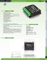
R525 R701/R710 MICROSTEPPING DRIVER MICROSTEPPING DRIVER STEP MOTORS FEATURES FEATURES INTEGRATED MOTORS • Bipolar Step Motor Driver • Operates from +24 to 80 VDC • Phase Current Ranges from 1 to 7 Amps or 0.3 to 2 Amps • 10x Microstepping Driver • Optically Isolated Step, Direction, and Disable/Enable Inputs • Selectable Current Reduction of 33% • Low Power Dissipation • Step Frequency of 200 kHz • Efficient Current Control • Power-On Indicator • Power Disable/Enable Control • Sinusoidal Current Waveform • Low Cost Driver SPECIFICATIONS DIMENSIONS SPECIFICATIONS • INPUT VOLTAGE: +24 to 80 VDC • DRIVE CURRENT(PER PHASE): 0.3 to 2.0 Amps or 1 to 7 Amps • ISOLATED INPUTS: Step Clock, Direction, Disable • STEP FREQUENCY (MAX): 200 kHz • STEPS PER REVOLUTION (1.8˚ MOTOR): 2000 • MicrOstep Resolutions (1.8˚ MOTOR): 10x CUSTOM DESIGNS • INPUT VOLTAGE: +12 to 75 VDC • DRIVE CURRENT(PER PHASE): 0.1 to 5.0 Amps Peak in 0.05 Amp increments • ISOLATED INPUTS: Step, Direction, and Disable • STEP FREQUENCY (MAX): 5 MHz • STEPS PER REVOLUTION (1.8 MOTOR): 200, 400, 800, 1600, 2000, 3200, 5000, 6400, 10000, 12800, 25000, 25600, 50000, 51200 • MicrOstep Resolutions (1.8˚ MOTOR): Full, 2X, 4X, 5X, 8X, 10X, 16X, 25X, 32X, 50X, 64X,125X, 128X, 250X, 256X • POLE DAMPING TECHNOLOGYTM: See page 8 R710 - includes a built-in Step Pulse Multiplier board The R710 has the same features as the R701 plus two additional features: • Input Option Header: Allows the use of a Common Ground or a Common +5VDC for optically isolated inputs • Step Pulse Multiplier: The R701 will always output 10 microstepping, even with a step input of Full Step, Half Step, 5 Microstep, or 10 Microstep. The user no longer needs to change their original setup to get microstepping. Simply select the desired step multiplier of 1, 2, 5 or 10; to achieve the 10 microstepping output from the driver, while maintaining the rotational speed that you had in your original setup. BLDC MOTORS • Operates from +12 to 75 VDC • Software selectable run currents from 0.1 to 5.0 Amp Peak (in 0.05 Amp increments) • Software selectable hold currents from 0.1 to 5.0 Amp Peak (in 0.05 Amp increments) • Step Resolutions from Full, 2x, 4x, 5x, 8x, 10x, 16x, 25x, 32x, 50x, 64x, 125x, 128x, 250x, 256x Microstepping • Four Selectable Damping modes for smooth motion • No low minimum inductance • Step sensing on the rising or falling edge of step pulse input • Direction switching – to change initial powered on direction of rotation • Disable active high or low – to allow unit to be disabled with a high or low signal • Smooth motion • Three optically isolated control inputs (step, direction, disable) • Inputs are sinking inputs, maximum current input is 15mAmps • Pole DampingTM Technology - Integrated within driver board (see page 8) DIMENSIONS 3.31 ACCESSORIES 0.65 0.81 1.32 0.80 2.71 0.15 0.29 0.34 0.91 1.63 2.60 2.75 RMS TECHNOLOGIES 2.77 1.45 0.150 THRU (4X) 2.15 0.81 0.57 0.34 0.64 0.21 3.00 103 103 16245 Vineyard Blvd, Morgan Hill, CA 95037 - Tel. 408-919-0200 - Fax. 408-919-0201 - [email protected] - www.linengineering.com 104
Open the catalog to page 1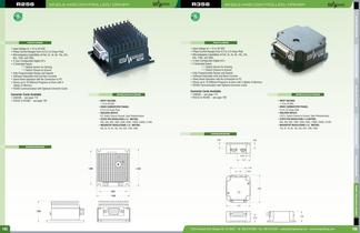
R256 SINGLE AXIS CONTROLLER/ DRIVER R356 SINGLE AXIS CONTROLLER/ DRIVER STEP MOTORS FEATURES FEATURES • USB485 - see page 110 • RS232 to RS485 - see page 109 Converter Cards Available SPECIFICATIONS • USB485 - see page 110 • RS232 to RS485 - see page 109 SPECIFICATIONS DIMENSIONS 0.56 0.58 CUSTOM DESIGNS • INPUT VOLTAGE: +12 to 40 VDC • DRIVE CURRENT(PER PHASE): 0.3 to 3.0 Amps Peak • ISOLATED INPUTS: 4 I/O’s, Switch Closure to Ground, Opto Phototransistor • STEPS PER REVOLUTION (1.8 MOTOR): 200, 400, 800, 1600, 3200, 6400, 12800, 25600, 51200 • MicrOstep Resolutions (1.8˚ MOTOR): Full, 2x, 4x,...
Open the catalog to page 2All Lin Engineering catalogs and technical brochures
 SilverPak 17D Plus
1 Page
 5818 ?Super Torque
1 Page
 4518 ? Signature Series
1 Page
 208 ? Standard Motor
1 Page
 High Torque
1 Page
 Why Lin 2014
2 Pages
 R208
R2083 Pages
 8718 HIGH TORQUE MOTOR
1 Page
 8618 STANDARD MOTOR
1 Page
 5718 HIGH TORQUE MOTOR
1 Page
 5618 STANDARD MOTOR
1 Page
 5609 STANDARD MOTOR
1 Page
 5704 HIGH ACCURACY MOTOR
1 Page
 4418 XTREME TORQUE MOTOR
1 Page
 4118 SUPER TORQUE MOTOR
1 Page
 4018 STANDARD MOTOR
1 Page
 4209 HIGH TORQUE MOTOR
1 Page
 4109 GOLD LINE MOTOR
1 Page
 3518 STANDARD MOTOR
1 Page
 211 COMPACT MOTOR
1 Page
 208 COMPACT MOTOR
1 Page
 SilverPak 17C/CE
2 Pages
 SILVERPAK 23D/DE
3 Pages
 SilverPak 23C
2 Pages
 GOLD LINE MOTOR
2 Pages
 MODULAR MOTOR 3609 SERIES
2 Pages
 1.8° SIZE 11
2 Pages
 STANDARD MOTOR
2 Pages
 SilverPak 17T
3 Pages
 1.8º SIZE 14
2 Pages
 HIGH TORQUE MOTOR 3509V
2 Pages
 Lin Catalog 2006
100 Pages


Archived catalogs
 STANDARD MOTOR 8618
2 Pages
 STANDARD MOTOR 5609
2 Pages
 SUPER TORQUE MOTOR 4118
2 Pages
 SUPER TORQUE MOTOR 4118
2 Pages
 STANDARD MOTOR 4018
2 Pages
 HIGH TORQUE MOTOR 4209
2 Pages

- Electromotor
- DC electromotor
- Actuator
- Multipole motor
- Angular encoder
- Linear actuator
- Planetary gearbox
- Electric actuator
- Coaxial gearhead
- Incremental encoder
- Precision gearhead
- 24 V motor
- Incremental rotary encoder
- Solid-shaft gearhead
- Compact electromotor
- 2-pole motor
- 12 V motor
- Absolute rotary encoder
- Gearbox for industrial applications
- Stepper motor