
Catalog excerpts
FRONT COVER
Open the catalog to page 1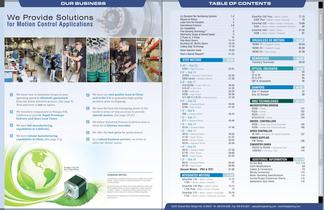
for Motion Control Applications We know how to maximize torque at your operating speed to eliminate guesswork from the motor selection process. (See page 9) Trial and error is not an option. We inventory components in Morgan Hill, California to provide Rapid Prototype Delivery and Short Lead Times. We have full manufacturing We have volume manufacturing capabilities in China. (See page 5-6) Q We have our own quality team in China and in the U.S. to guarantee high quality products prior to shipping. Q We have the best microstepping motor in the world in terms of step accuracy to provide...
Open the catalog to page 2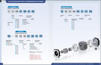
LIN STANDARD PART NUMBERING SYSTEMS Special Modifications Special Features Special Identifiers T: Noise Reduced Connection Integrated Motors Only (SilverPak Series) Frame Size Winding Code Overall Length Special Modifications Special Features Special Identifiers T: Noise Reduced Connection R: Noise Reduced Winding M: Mounting option for 3709 motors* Any Size 34 motor without a "S" or "P" have eight leads standard and M1, SIGNATURE, CAST MTG SIZE 17, #4-40 UNC M2, SIGNATURE, CAST MTG SIZE 17, M3 X 0.5 M3, SIGNATURE, CAST MTG SIZE 17, 0.130 THRU M4, SIGNATURE, CAST MTG SIZE 14, #4-40 UNC M5,...
Open the catalog to page 3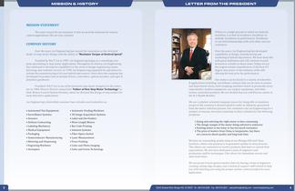
MISSION & HISTORY MISSION STATEMENT The main reason for our existence is that we provide solutions for motion control applications. We are your solution. COMPANY HISTORY Over the years Lin Engineering has earned the reputation as the technical leader in step motor design with the ability to “Maximize Torque at Desired Speed”. Founded by Ted T. Lin in 1987, Lin Engineering began as a consulting company specializing in step motor applications. Throughout its history, Lin Engineering has continued to develop its capabilities in the areas of design engineering, manufacturing, and customer...
Open the catalog to page 4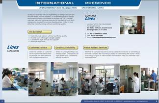
UN ENGINEERING'S ASIA HEADQUARTERS Scale your business with Lin Engineering at design and pre-pro- duction levels. At low volumes, Lin Engineering has full design and manufacturing capabilities in Morgan Hill, CA. For high volumes, we have a proven process for transferring both tech- nology and product to our Asia Headquarters, Linex, for cost effective manufacturing without sacrificing quality. V Cost effective solution without sacrificing quality V Double source through a single supplier V Consistently high service and support V Minimize lead times Customer Service j [ Quality &...
Open the catalog to page 5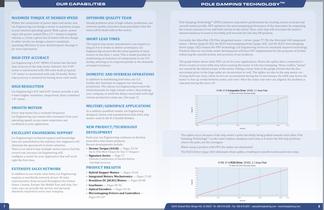
OUR CAPABILITIES Within the constraints of power input and motor size, Lin Engineering can design a motor to maximize torque at your desired operating speed. With a given power input, the power output ƒTd ω ( T = torque at angular velocity ω ) from a given size of motor will not change. In other words, we design a motor’s maximum operating efficiency at your desired speed. See page 9 for more information. Maximize Torque at Desired Speed Lin Engineering’s 0.45° NEMA 23 motor has the best step accuracy in the step motor industry. Our 0.45° motor is constructed with 200 rotor teeth (a typical...
Open the catalog to page 6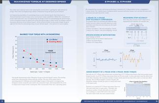
MAXIMIZING TORQUE AT DESIRED SPEED One of the most common issues with selecting the correct motor is getting the right amount of torque. That's how Lin Engineering's ability to Maximize Torque @ Speed can be utilized. Lin Engineering specializes in maximizing torque at your desired speed. Each step motor is characterized by its speed-torque curve, or, its power output capabilities. Within the constraints of power input and motor size, Lin Engineering can design a motor by manipulating the speed-torque curve to maximize torque in a given area across the speed range. In other words, we design...
Open the catalog to page 7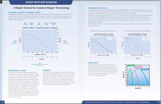
STEP MOTOR BASICS A Simple Tutorial for Common Stepper Terminology READING A SPEED & TORQUE CURVE The graph below depicts the relationship between speed and torque while a step motor is running. The output torque is very critical during the motor selection process. On the graph, the vertical y-axis represents torque (oz-in and N-m) while the horizontal x-axis represents the speed of the motor's torque (oz-in) Phase Connection Microstepping Current Scheme Setting represents the speed of the motor's shaft ROTATIONAL SPEED Step motors rotate continuously when given a specific series of pulses....
Open the catalog to page 8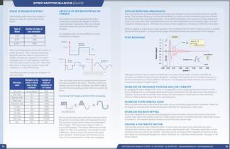
STEP MOTOR BASICS (Cont'd) The following table shows the number of pulses, or steps, for a given type of step When microstepping the motor, the number of pulses increases. This is because microstep- ping will cause the motor to step in finer, or smaller, increments. Instead of a 1.8° motor stepping every 1.8°, half stepping it will then force the motor to move every 0.9°. The motor then needs to step twice as much to go 1 full revolution, or a total of 400 steps. The following table provides the multiplier for each microstep: The amount of current going from the driver to the motor...
Open the catalog to page 9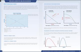
BRUSHLESS DC (BLDC) BASICS how to read bldc curves The graph below provides three main motor specifications that can help users determine whether or not this BLDC motor is sufficient for the job. The left-side vertical Y-axis represents speed in revolutions per minute (RPM). The speed increments and the title “Speed (RPM)” are blue, which corresponds to the blue curve on the graph. The right-side vertical Y-axis represents Current in Amps. This axis is red, which corresponds to the red line on the graph. The horizontal X-axis is for torque in ounce-inches (oz-in). EXPLANATION OF AXIS...
Open the catalog to page 10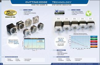
CUTTING EDGE TECHNOLOGY FROM THE LEADER IN S T E P M O T O R I N N O V AT I O N FOR: FOR: * Smooth Motion * High Accuracy & Reliability * Low Noise * High Torque & Reliability * Energy & Space Efficiency * Low Noise 100 oz-in Holding Torque 71 oz-in 61 oz-in Holding Torque 37 oz-in Holding Torque 27 oz-in Holding Torque Holding Torque Xtreme Torque 4418S Series Comparison 1.8º Step Motor, 24VDC, Rated Current, Bipolar, 1/2 Stepping 60.00 35% Resonance by up to Lin’s Standard 4118S 40.00 MORE TORQUE 30.00 with the SAME POWER INPUT 50% Motor length: 1.35” 50.00 Get Up to Reduce System Lin’s...
Open the catalog to page 11All Lin Engineering catalogs and technical brochures
-
SilverPak 17D Plus
1 Pages
-
IP65 & IPX7 Vacuum Motors
1 Pages
-
5818 ?Super Torque
1 Pages
-
4518 ? Signature Series
1 Pages
-
208 ? Standard Motor
1 Pages
-
High Torque
1 Pages
-
Why Lin 2014
2 Pages
-
MICROSTEPPING DRIVER
2 Pages
-
R208
3 Pages
-
8718 HIGH TORQUE MOTOR
1 Pages
-
8618 STANDARD MOTOR
1 Pages
-
5718 HIGH TORQUE MOTOR
1 Pages
-
5618 STANDARD MOTOR
1 Pages
-
5609 STANDARD MOTOR
1 Pages
-
5704 HIGH ACCURACY MOTOR
1 Pages
-
4418 XTREME TORQUE MOTOR
1 Pages
-
4118 SUPER TORQUE MOTOR
1 Pages
-
4018 STANDARD MOTOR
1 Pages
-
4209 HIGH TORQUE MOTOR
1 Pages
-
4109 GOLD LINE MOTOR
1 Pages
-
3518 STANDARD MOTOR
1 Pages
-
3809 SERIES MODULAR MOTOR
1 Pages
-
211 COMPACT MOTOR
1 Pages
-
208 COMPACT MOTOR
1 Pages
-
SilverPak 17C/CE
2 Pages
-
SILVERPAK 23D/DE
3 Pages
-
SilverPak 23C
2 Pages
-
GOLD LINE MOTOR
2 Pages
-
MODULAR MOTOR 3609 SERIES
2 Pages
-
1.8° SIZE 11
2 Pages
-
STANDARD MOTOR
2 Pages
-
SilverPak 17T
3 Pages
-
1.8º SIZE 14
2 Pages
-
HIGH TORQUE MOTOR 3509V
2 Pages
-
Lin Catalog 2006
100 Pages
Archived catalogs
-
SUPER TORQUE MOTOR 4118
2 Pages
-
STANDARD MOTOR 5609
2 Pages
-
STANDARD MOTOR 4018
2 Pages
-
STANDARD MOTOR 8618
2 Pages
-
SUPER TORQUE MOTOR 4118
2 Pages
-
HIGH TORQUE MOTOR 4209
2 Pages


