Catalog excerpts
REACTIVE POWER COMPENSATION OF HIGH VOLTAGE POWER SYSTEMS >
Open the catalog to page 1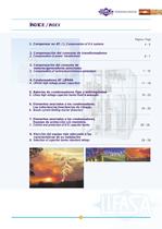
P͡gina / Page 1. Compensar en AT. / > 1. Compensation of H.V. systems 4 - 5 2. Compensacin del consumo de transformadores > 2. Compensation of power transformers 6 - 77 - 1011 - 1819 - 23 26 - 2824 - 25 28 - 29 3.Compensacin del consumo de motores/generadores as㳭ncronos > 3.Compensation of motors/asynchronous generators 4.Condensadores AT LIFASA > 4.LIFASA high voltage power capacitors 5. Bateras de condensadores fijas y autoreguladas > 5. Lifasa high voltage capacitor banks-fixed & automatic 6.Elementos asociados a los condensadores.Las inductancias/reactancias de choque. > 6.Inrush...
Open the catalog to page 2
La duda sobre cmo y dnde compensar aparece en instalacionesque distribuyen en BT, pero contratan en AT. Para ver qu㳩 nos interesa ms, se deben conocer los consumos de energa reactiva con la finalidad de calcular la potencia necesaria. Se estudiar᭡ la posible existencia de un consumo constante elevado que sera el objetivo en AT. Como orden de magnitud, este consumo debe de estar alrededor de 1 Mvar, dependiendo de las tensiones de servicio en AT.Normalmente, en la mayora de los casos estas instalaciones seacaban compensando en BT.Por otro lado en grandes industrias donde se consume energaen...
Open the catalog to page 3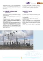
tion demands higher investment. In both type it is necessary toobtain an optimum value of power factor with a most economical capacitor installation. The capacitor installation could be fixed or automatic type. ms econmico. Los equipos podr᳡n ser fijos o automticos, igual que en BT. > Econmicamente, la reducciᳳn de la energa reactiva a suministrarpor la red proporciona: Supresi핳n o reduccin de las penalidades por consumo deE. Reactiva.Tcnicamente las ventajas son :㩕 Aumento de la potencia disponible de los transformadores. Reducciճn de prdidas de potencia en las lneas, asociada a la...
Open the catalog to page 4
Power transformer is one of the major consumer of reactive powerand installing capacitors with power transformer for total con-nected load has various technical advantages. Uno de los principales consumidores de E. Reactiva en AT y quese beneficia de las ventajas tcnicas de la colocaci㩳n de un equipo propio que aporte la E. Reactiva necesaria para las cargas, son los Transformadores de Potencia. For determining the total reactive power losses we have to considerthe magnetising current, which is practically constant from no load to full load condition, and on account of it no load power of...
Open the catalog to page 5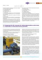
El otro tipo de carga que nos encontramos ms habitualmenteen instalaciones de AT es el Motor/Generador Asncrono, es delos receptores m᭡s importantes y con una mayor presencia en instalaciones AT/AT. La compensacin de este tipo de cargas la podemos llevar a cabo en nuestras redes utilizando tres mtodos posibles: Another type of major load, which are normally connected to highvoltage net work is motors/asynchronous generators. This is avery important installation and requires a lot of attention in ins- talling, operating and maintaining. For the reactive power compensation of this type of...
Open the catalog to page 6
In A.C. machine, the reactive power is to the order of 30 - 40% ofits rated power. Therefore it is a major consumer of reactive power from system. Normally, power factor correction of this type of installations is done by connecting a capacitor bank of suitable rating directly to the terminals of the motor.The switchgear, controls and protective system of machine operateboth capacitor and machine simultaneousely. This is the most common and economical method used for reactive power compensation of rotating machines. However for more feasibility inoperation and maintenance of capacitor, it...
Open the catalog to page 7
Potencia Nominal (kW) Cos inicial segn placa / Cos initial Cos inicial segn placa / Cos initial Motor Rating (kW) Caracter꺭sticas motor (0,8) Caractersticas motor (0,85) Cos initial of motor (0,8) Cos initial of motor (0,85) Cos final / Cos final Cos final / Cos final En este tipo de configuracin de nuestra instalacin, conseguimosevitar un posible riesgo de autoexcitaci㳳n y podemos compensarnuestra red con un cos ms prximo a 1,00. Utilizaremos elementos de maniobra y/o protecciᳳn independientes para motor y condensador, de tal manera que enclavadas las dos, al parar el motor ponemos fuera...
Open the catalog to page 8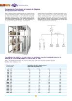
Ante la situaci㡳n anterior podramos optar por nuestra solucincompacta de batera automtica, en la que encontramos un equipo de dimensiones optimizadas, que con la utilizacin de regulador autom᳡tico realiza de manera automatizada, al igual que las bateras de condensadores en BT, la conexin/desconexin delos condensadores, adaptndonos en cada momento a lacompensacin del rᳩgimen de cargas de la instalacin. Modern method of compensation is automatic power factor correc-tion, for a group of motors. in a motor control centre. In this method, system power factor is improved to an optimum value with...
Open the catalog to page 9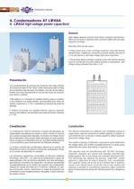
High voltage capacitor units for power factor correction and harmonicfilters are enclosed in stainless steel containers fitted with porcelain capacitor bushings.Basically, there are two types:? Single phase (one or two bushings) capacitor units with internalelement fuses suitable for connection to power system net work of 11 kV and above or with high voltage high power machines.? Three phase (three bushings) capacitor units with internal elementfuses for connection to power system busbars or equipments with voltage rating preferably less than 11 kV. > Los condensadores de potencia de...
Open the catalog to page 11
The surface of polypropylene film is rough (hazy) to make oilpenetration to internal film and foil layers faster and more effectiveat the time of impregnation and this has reduced the manufacturing time considerably. The aluminium foil edge inside the element is laser-cut to make it smooth and free from sharp points (which normally exist incase of blade cut foil edges). Thus the electric field at edge is reduced to increse the corona inception voltage level. Capacitor units have better withstand capability against over voltages and transients. Segn las recomendaciones de la Norma CEI...
Open the catalog to page 12All LIFASA catalogs and technical brochures


Archived catalogs
-
 LIFASA leaflet
8 Pages