
- Catalogs
- L.E.T. Automotive NV
- Gradient Scanning 10m Wall

Gradient Scanning 10m Wall
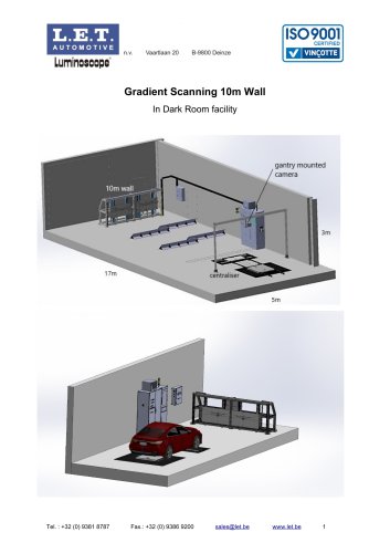
Gradient Scanning 10m Wall
Catalog excerpts
Gradient Scanning 10m Wall In Dark Room facility
Open the catalog to page 1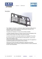
The ‘intelligent’ 10m wall is a construction, made of aluminium profiles and two white panels with specific markings, for interpreting and estimation of the headlamp images and their adjustment. The panels are motorised in Y/Z and can be remotely controlled. A centrally integrated red laser can project a laser dot onto the headlamp of the vehicle in front to refer to the centre or zero point of the lamp. A number of photocells is horizontally positioned and integrated in the panels. By moving the panels in both horizontal and vertical direction, a scan can be made of the headlamp image. All measurement...
Open the catalog to page 2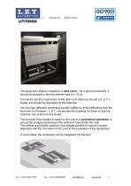
The equipment shall be installed in a dark room – for a good functionality, it should be possible to dim the ambient light to < 3 Lux. Civil works and the construction of the dark room itself are not part of L.E.T.’s supply and should be organized by the customer. Also the light reflection preventing wooden baffles (to avoid reflections from the floor) are not foreseen – L.E.T. can provide the drawings for these so that the customer can outsource this locally. The concept of the system is based on the use of a mechanical centralizer to ensure the straight positioning of the vehicle in front of...
Open the catalog to page 3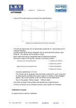
- Layout of the wall boards according to the specifications example of a possible layout for the 10m wall board - The left and right board can be electrically positioned in Y (horizontal) and Z (vertical) direction. Control components will be integrated into an extra electrical cabinet, type Rittal AE. The cabinet will be painted in black. - Each board will have an integrated laser for alignment purpose. Movement range of the boards, referred to the laser position: Left board intoo dnint Rn ho board intoo dnint Accuracy positioning: ± 0,1mm The boards will be equipped with photocells positioned...
Open the catalog to page 4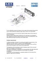
Phhole.S left Plnhoie.S right Laser right iOr_*oU For the calibration process, the lasers on the master will be directed through their two pin holes towards the reference laser holes in the two 10m wall panels. The panels will have to be moved such that the master lasers hit the location of the 10m wall lasers. Switching off the master lasers will allow the 10m wall lasers to be adjusted in their supporting mechanism behind the panel such that, by activating them, they pass perfectly through the pinholes of the master frame. Gradient measurement A software package is foreseen for scanning and...
Open the catalog to page 5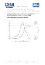
For saving a picture of the beam pattern, a separate camera in a protecting housing on a gantry or mounted to the ceiling of the dark room, can be supplied. This camera can take a picture of the beam pattern as projected on the 10m wall panels, which can then be stored for later use. The gradient curve is always calculated and stored as part of the standard supply. Reports and graphs can be consulted on a webpage. Example of intensity and gradient curves
Open the catalog to page 6All L.E.T. Automotive NV catalogs and technical brochures
 Speedoscope
2 Pages