- Catalogs
- LEROY-SOMER
- Moteurs asynchrones avec freins 160 au 315 HA
- Company
- Products
- Catalogs
- News & Trends
- Exhibitions
Moteurs asynchrones avec freins 160 au 315 HA
1 /85Pages

Moteurs asynchrones avec freins 160 au 315 HA
1 /85Pages
Catalog excerpts

Brake induction motors Frame sizes 160 to 315 Technical catalogue
Open the catalog to page 1
in 1886 by Marius PATAY, MOTEURS PATAY began by specializing in the production of electric motors and the PATAY trademark quickly became synonymous with high-performance products. The company is based in Lyon and has benefited from the region's rapid industrial expansion to expand into electromechanics and electrical engineering. Over the years, MOTEURS PATAY has become well-known throughout the world for offering innovative, technical solutions adapted to increasingly varied requirements. The company's reputation and expertise are especially relevant in the field of hoisting and handling applications....
Open the catalog to page 2
Brake induction motors FLSB - FCPL MOTORS . . . . . . . . . . . . . . . . . . . . . . . . 50 to 55 LSMV - FCPL MOTORS . . . . . . . . . . . . . . . . . . . . . . . . 26 to 31
Open the catalog to page 3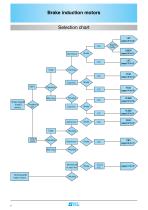
Drip-D proof Brake induction motors Selection chart Cage "LEROY' iSOMBi
Open the catalog to page 4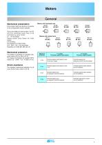
Mechanical presentation All our brake motors can be set up to operate in the configurations shown opposite. Due to the weight of some motors, the B5 and B14 mountings would have to be confirmed by Leroy Somer. V1 - V5 mountings: Please consult Leroy Somer for 2-disk brakes. V3 mounting: Not possible for 2-disk brakes. B14 - B34 - V18 - V19 mountings: Restricted to LS160 MP, MR and LR. Motors with horizontal axis IM B3 IM B5 Mechanical protection The degree of protection for standard drip-proof motors (PLS or PB) is IP 23. The degree of protection for standard TEFV motors (LS - LSMV - FLS -...
Open the catalog to page 5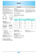
Motor terminal box In standard versions, the terminal box is mounted on top of the motor (position A), with the cable gland on the right (1) as viewed from the drive end. Due to the symmetrical construction of the terminal box, it can be placed in any of the four directions, except position 2 on flange-mounted motors. Connection Standard connection to the stator - Single-speed motor Connection via 6 terminals. - Multi-speed motors • 2 separate speeds Connection via 2 x 3 terminals, 3 terminals per speed. • Dahlander connection Connection via 6 terminals. Standard connection to the rotor of slip-ring...
Open the catalog to page 6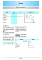
Characteristics Characteristic values Parameter Torque and current curve according to speed (Rated) (Synchronous) Type of rotor Aluminium rotor - ALU This is the most suitable type for continuous duty (S1, S2, S9 and S10) because of its optimum efficiency and power factor. However, in certain cases it can be used for intermittent duty. DP rotor This is the ideal rotor for periodic operation, since the starting torque is high whereas the current is low. It also reduces the torque drop of the aluminium rotor. This is the standard rotor used for intermittent duty motors and for 2-speed motors...
Open the catalog to page 7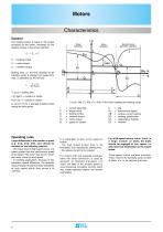
Df = braking torque Cr = resistive torque NS = synchronous speed DC = regenerative braking EF = reversal General The braking torque is equal to the torque produced by the motor, increased by the resistive torque of the driven machine. Cf = Cm + Cr Cf = braking torque Cm = motor torque Cr = resistive torque Braking time, i.e. the time required for an induction motor to change from speed N to stop, is calculated by the formula: T = n ■ J - IN f 30 ■ Cf(av) Tf (in s) = braking time J (in kgm2) = moment of inertia N (in min-1) = speed of rotation Cf (av) (in N.m) = average braking...
Open the catalog to page 8
Operating factor Expressed as a percentage, this is the ratio of the motor power-up time during the cycle to the total cycle time, provided that the total cycle time is less than 10 minutes. Starting class Class = N = Nd + K.Nf + K'.Ni Nd: number of complete starts per hour Nf: number of electrical braking operations (deceleration) per hour Ni: number of pulses (incomplete starts up to a third of maximum speed) per hour Constants K and K' have the following values: cage motors: K = 3 K' = 0.5 slip-ring motors: K = 0.8 K' = 0.25 An electrical braking operation is defined as an operation...
Open the catalog to page 9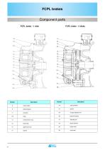
"LEROY' iSOMBi
Open the catalog to page 10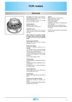
D.C. brake, FCPL series, 65 to 2400 Nm, separate power supply by rectifier or doping device depending on size. It can be mounted on IP 23 or IP 55 cage rotor or wound rotor motors. Brake protection Standard version IP 44. Brake protected by a steel cover. Conditions of use There are two types of coil, one for continuous duty (S1) and one for intermittent duty (S3). When ordering, it is essential to specify the type of duty, as well as the number of starts per hour and the operating factor. Options Brake voltage (20 V, 100 V, 200 V). Release by a lever (DLRA). Brake release indicator. Lining wear...
Open the catalog to page 11
* Operation with CDF device. (1) Can operate without a CDF device. The maximum air gap before adjustment is limited to 1.2 mm. 1) Description When stationary, the coil 9 is not energised, the disk 15 sliding on a splined sleeve is pressed between the armature 11 and the plate 8 by action of the springs 28. The motor rotor rotation is stopped. The air gap is between the yoke 9 and the armature 11. When the coil 9 is energised, the armature 11 is attracted, the springs are compressed, the disk 15 and the rotor are released. On braking, disconnection of the current eliminates the magnetic field,...
Open the catalog to page 12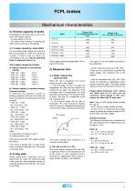
braking - FCPL 40 - 1 disk: - 35 kJ 3) Thermal capacity of brake Overheating of the brake and its coil is the sum of the losses caused: - by Joule effect in the coil - by friction when braking or starting the motor when the brake is still applied. 3-1) Losses caused by Joule effect For a constant supply voltage, the current in the coil is constant (I = U/R). As a result, the number of starts has no effect on overheating of the coil, only the operating factor is important (see 5-1-a). 3-2) Losses caused by friction a) Thermal capacity on non periodic b) Thermal capacity on periodic braking...
Open the catalog to page 13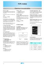
FCPL 60 - 2 disks: The brake release time is the same as for the 1-disk FCPL set to half the torque of the 2-disk FCPL. These values are given for a rectifier power supply. FCPL 88 - 1 or 2 disks: - ta = 150 ms b) The tolerance on the voltage supply The tolerance on the supply voltage to the coil terminals is ± 10 %. A reduced power supply increases the response time. The CDF doping device helps to avoid the effects of supply voltage fluctuations. c) The size of the air gap The brake response time depends on the size of the air gap setting. This time can be multiplied by 3 when the air gap is...
Open the catalog to page 14All LEROY-SOMER catalogs and technical brochures
 IMfinity® 3-phase induction motors
152 Pages
 FFB brake motors
52 Pages
 Brake motors range
16 Pages
 POULIBLOC
8 Pages
 DYNABLOC
100 Pages
 IMfinity® ATEX induction motors
16 Pages
 MULTIBLOC - IMfinity
88 Pages
 Cb, Ot, Mub, Mb, FFB
84 Pages
 LS FFB - LSES FFB
52 Pages
 LSK
LSK164 Pages
 asynchrones triphasés
176 Pages
 INDUCTION MOTORS
60 Pages
 Electromechanical drive systems
20 Pages
 Powerdrive MD2 & Systemiz
2 Pages
 Industrial Refrigeration
16 Pages
 Energy Efficiency Solutions
24 Pages
 Proxidrive
2 Pages
 Digistart D3
8 Pages
 Multibloc
2 Pages
 Training Courses 2018
52 Pages
 Environmental Policy
2 Pages
 Express Availability Commitment
12 Pages
 LEROY-SOMER QUALITY POLICY
2 Pages
 Port Logistics
20 Pages
 Hydroelectricity
2 Pages
 Nuclear Applications
16 Pages
 Marine Applications
20 Pages
 Minerals Industry
12 Pages
 Crane and hoist solutions
16 Pages
 Unimotor
2 Pages
 LC liquid cooled motors
92 Pages
 Induction motors for axial fans
60 Pages
 3-phase induction motors
176 Pages
 Geared motors 3000 Range
16 Pages
 IMfinity® induction motor range
20 Pages
 FFB brake motors
24 Pages
 TAL 040 - TAL 042 - TAL 044
36 Pages


Archived catalogs

- Synchronous motor
- LEROY SOMER AC motor
- LEROY SOMER multipole motor
- LEROY SOMER gear-motor
- LEROY SOMER asynchronous motor
- LEROY SOMER three-phase motor
- Precision gearhead
- Servo-motor
- Compact gearhead
- LEROY SOMER 4-pole motor
- Solid-shaft gearhead
- LEROY SOMER 2-pole motor
- High-efficiency electromotor
- LEROY SOMER IP55 motor
- LEROY SOMER compact motor
- Gear train gear reducer
- LEROY SOMER 380 V motor
- Permanent magnet motor
- Machining service