- Catalogs
- LEROY-SOMER
- LS FFB - LSES FFB
- Company
- Products
- Catalogs
- News & Trends
- Exhibitions
LS FFB - LSES FFB
1 /52Pages

LS FFB - LSES FFB
1 /52Pages
Catalog excerpts

IMfinity® FFB brake motors Standard Efficiency Not Concerned by IE Standards and IE3 High Efficiency Variable speed and Fixed speed Frame size from 71 to 180 Power from 0.25 to 18.5 kW
Open the catalog to page 1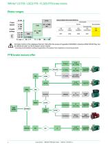
IMfinity® LS FFB - LSES FFB - FLSES FFB brake motors FCPL Fixed speed 4-pole brakes 15 kW 11 kW 9 kW Associated documentations Environment Normal Dust-protected 2 Leroy-Somer - IMfinity® FFB brake motors - 5329 en - 2018.03 / g
Open the catalog to page 2
IMfinity® LS FFB - LSES FFB - FLSES FFB brake motors SOLID SHAFT HOLLOW SHAFT SOLID SHAFT HOLLOW SHAFT SOLID SHAFT HOLLOW SHAFT SOLID SHAFT Associated Drives ranges LS IFT/NIE Variable speed Leroy-Somer - IMfinity® FFB brake motors - 5329 en - 2018.03 / g 3
Open the catalog to page 3
IMfinity® LS FFB - LSES FFB - FLSES FFB brake motors Contents INTRODUCTION IDENTIFICATION - INSTALLATION Leroy-Somer - IMfinity® FFB brake motors - 5329 en - 2018.03 / g
Open the catalog to page 4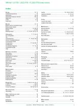
Leroy-Somer - IMfinity® FFB brake motors - 5329 en - 2018.03 / g
Open the catalog to page 5
IMfinity® LS FFB - LSES FFB - FLSES FFB brake motors 6 Leroy-Somer - IMfinity® FFB brake motors - 5329 en - 2018.03 / g
Open the catalog to page 6
IMfinity® LS FFB - LSES FFB - FLSES FFB brake motors Construction Mounting forms and operating positions Foot mounted Optional cable gland positions Standard position BOTTOM Foot mounted motor A - Top: standard Flange mounted motor A - Top: standard Leroy-Somer - IMfinity® FFB brake motors - 5329 en - 2018.03 / g
Open the catalog to page 7
IMfinity® LS FFB - LSES FFB - FLSES FFB brake motors Operation Definition of the brake motor The brake motor combines, in a single electromechanical assembly - a motor: rotor + stator which forms the drive mechanism - control device: electromagnet + a springs which apply or release the brake, - friction: lining + mating surface which provide the braking action. AERAS OF USE • Intermittent duty: a mechanical device driven by a motor on its own takes a long time to stop if there is little friction. The brake motor ensures shorter, accurate and safe stopping times. It is used in handling where accuracy...
Open the catalog to page 8
IMfinity® LS FFB - LSES FFB - FLSES FFB brake motors Operation Duty cycle definitions CONDITIONS AND DUTY CYCLES CONDITIONS By condition”, we mean all the electrical and mechanical values that typify machine operation at a given time. Load Charge DUTY CYCLES (according to IEC 60034-1) By duty”, we mean the stipulated conditions to which the machine is subjected, their respective durations and order of succession over time. 1 - Continuous duty - Type S1 Operation at constant load of sufficient duration for thermal equilibrium to be reached (see figure 1). 5 starts maximum per hour. Fig. 4. - Intermittent...
Open the catalog to page 9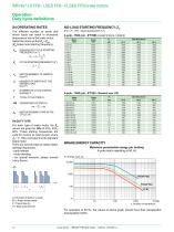
IMfinity® LS FFB - LSES FFB - FLSES FFB brake motors Operation Duty cycle definitions S4 OPERATING RATES The different number of starts and driven loads can result in excessive temperature rise in the brake motor. Select the motor so that Zo > Zoc (Zo brake motor starting frequency). NO-LOAD STARTING FREQUENCY: Zo (For AT = 100°, values expressed in h-1) 4-pole - 1500 rpm - IFT/NIE (except motors in italics) Motor Brake Pn _ Zc : CYCLE STARTING FREQUENCY (h-1) Jm : MOTOR MOME NT OF INERTIA m (kg.m2) Jc : MOMENT OF INERTIA OF THE DRIVEN LOAD (kg.m2) n : NUMBER OF CYCLE STARTS DURING T T...
Open the catalog to page 10
IMfinity® LS FFB - LSES FFB - FLSES FFB brake motors The DC electromagnet consists of a resin-coated coil in a cast iron yoke. The yoke and the armature form the magnetic circuit. All our coils are made for a DC voltage of 180 VDC (400 or 230 VAC supply) or 20 VDC (24 VAC supply). All the electromagnets are class F and can be continuously supplied with power. Maximum permissible voltage in S1 duty is 480 V, for any product. Since it is difficult to distinguish between some DC coils by size alone, the coil resistance should be measured with an appropriately rated ohmmeter and compared with the...
Open the catalog to page 11
IMfinity® LS FFB - LSES FFB - FLSES FFB brake motors The braking torque Mf is obtained from the friction between a lining made of fibrous composite material and a mating surface. If the braking torque is higher than the highest motor torque, there is a risk of the drivetrain becoming fatigued or breaking. It is therefore advisable to use: Mf = 1.5 x Mn and never to exceed Md. The stated dynamic braking torque is optimum (tolerance from -10 to +40%). A standard is determined as a function of the motor power and its efficiency class: see the selection tables in the Characteristics Tables section. A...
Open the catalog to page 12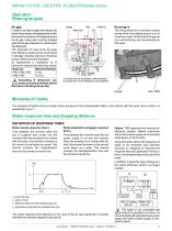
IMfinity® LS FFB - LSES FFB - FLSES FFB brake motors Its replacement is mandatory as R dimension reaches the following values: Frein brake A This option is not compatible with motors for operation on a drive. It is not compatible with separate brake power supply (and built-in power supply on two-speed motors). In: rated current t1: Release response time (milliseconds ms) t2: Application response time (milliseconds ms) The brake response time depends on the value of the air gap adjustment. It should therefore be checked regularly (see above) Leroy-Somer - IMfinity® FFB brake motors - 5329 en -...
Open the catalog to page 13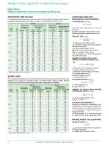
RESPONSE TIME VALUES The response times below are given for a brand-new brake (air gap at its rated value), supplied independently of the motor and at a coil temperature of 20°C ±5 %. Brake type Brake release response time t1 (ms) Standard TRR1 Response time brake application t2 (ms) 1. Sound pressure shall be measured at 1 metre Jf. Moment of inertia rotating at (in kgm2) wN: Motor angular speed (in rd/s) J2: Moment of inertia rotating at (in kgm2) w2: Angular speed (in rd/s) m: Mass travelling at (in kg) v: Linear speed (in m/s) STOPPING DISTANCE (in m): [a la = v fa + t2 + ~2 v: Linear...
Open the catalog to page 14
IMfinity® LS FFB - LSES FFB - FLSES FFB brake motors Operation Loads applied to the motor (main) shaft In pulley and belt couplings, the shaft extension carrying the pulley is subjected to a radial force. Formulae and charts can be read in the IMfinity® Motors catalog ref.5147. In the same catalog, the axial force on the shaft can be found for a bearing life L10h of 25,000 and 40,000 hours. EXAMPLE OF SELECTION CUSTOMER REQUEST: Normal, non-corrosive environment, General applications. 0.75 kW 4p brake motor for motorizing a 15-tonne trolley. - Linear speed: 15 m/min - Accuracy on stopping: to...
Open the catalog to page 15All LEROY-SOMER catalogs and technical brochures
 IMfinity® 3-phase induction motors
152 Pages
 FFB brake motors
52 Pages
 Brake motors range
16 Pages
 POULIBLOC
8 Pages
 DYNABLOC
100 Pages
 IMfinity® ATEX induction motors
16 Pages
 MULTIBLOC - IMfinity
88 Pages
 Cb, Ot, Mub, Mb, FFB
84 Pages
 LSK
LSK164 Pages
 asynchrones triphasés
176 Pages
 INDUCTION MOTORS
60 Pages
 Electromechanical drive systems
20 Pages
 Powerdrive MD2 & Systemiz
2 Pages
 Industrial Refrigeration
16 Pages
 Energy Efficiency Solutions
24 Pages
 Proxidrive
2 Pages
 Digistart D3
8 Pages
 Multibloc
2 Pages
 Training Courses 2018
52 Pages
 Environmental Policy
2 Pages
 Express Availability Commitment
12 Pages
 LEROY-SOMER QUALITY POLICY
2 Pages
 Port Logistics
20 Pages
 Hydroelectricity
2 Pages
 Nuclear Applications
16 Pages
 Marine Applications
20 Pages
 Minerals Industry
12 Pages
 Crane and hoist solutions
16 Pages
 Unimotor
2 Pages
 LC liquid cooled motors
92 Pages
 Induction motors for axial fans
60 Pages
 3-phase induction motors
176 Pages
 Geared motors 3000 Range
16 Pages
 IMfinity® induction motor range
20 Pages
 FFB brake motors
24 Pages
 TAL 040 - TAL 042 - TAL 044
36 Pages


Archived catalogs

- LEROY SOMER electric motor
- Synchronous motor
- LEROY SOMER AC motor
- LEROY SOMER multipole motor
- LEROY SOMER gear-motor
- LEROY SOMER asynchronous motor
- LEROY SOMER three-phase motor
- Precision gearhead
- Servo-motor
- Compact gearhead
- LEROY SOMER 4-pole motor
- Solid-shaft gearhead
- LEROY SOMER 2-pole motor
- High-efficiency electromotor
- LEROY SOMER IP55 motor
- LEROY SOMER compact motor
- Gear train gear reducer
- LEROY SOMER 380 V motor
- Permanent magnet motor
- Machining service