- Catalogs
- Leine & Linde
- Shielding connection
Shielding connection
1 /4Pages
Shielding connection
1 /4Pages
Catalog excerpts

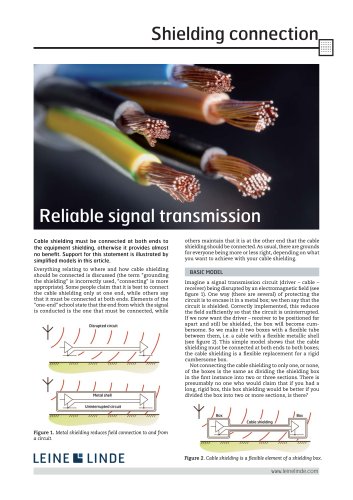
www.leinelinde.com Reliable signal transmission Cable shielding must be connected at both ends to the equipment shielding, otherwise it provides almost no benefi t. Support for this statement is illustrated by simplifi ed models in this article. Everything relating to where and how cable shielding should be connected is discussed (the term "grounding the shielding" is incorrectly used, "connecting" is more appropriate). Some people claim that it is best to connect the cable shielding only at one end, while others say that it must be connected at both ends. Elements of the "one-end" school state that the end from which the signal is conducted is the one that must be connected, while others maintain that it is at the other end that the cable shielding should be connected. As usual, there are grounds for everyone being more or less right, depending on what you want to achieve with your cable shielding. Figure 1. Metal shielding reduces fi eld connection to and from a circuit. Figure 2. Cable shielding is a fl exible element of a shielding box. Imagine a signal transmission circuit (driver – cable – receiver) being disrupted by an electromagnetic fi eld (see fi gure 1). One way (there are several) of protecting the circuit is to encase it in a metal box; we then say that the circuit is shielded. Correctly implemented, this reduces the fi eld suffi ciently so that the circuit is uninterrupted. If we now want the driver – receiver to be positioned far apart and still be shielded, the box will become cumbersome. So we make it two boxes with a fl exible tube between them, i.e. a cable with a fl exible metallic shell (see fi gure 2). This simple model shows that the cable shielding must be connected at both ends to both boxes; the cable shielding is a fl exible replacement for a rigid cumbersome box. Not connecting the cable shielding to only one, or none, of the boxes is the same as dividing the shielding box in the fi rst instance into two or three sections. There is presumably no one who would claim that if you had a long, rigid box, this box shielding would be better if you divided the box into two or more sections, is there? BASIC MODEL Shielding connection
Open the catalog to page 1
www.leinelinde.com Experience has shown that the signal transmission and the equipment function when the cable shielding is connected at both ends and when it is only connected at one end. There are explanations for this, but let's fi rst look at the basic principles of cable shielding. Another variant is that the signal transmission and the equipment function despite the fact that the cable shielding is not connected at all to any box, but then the cable shielding is not needed for any reason other than mechanical! This instance can also be electrically inferior to having at least one connection;...
Open the catalog to page 2
www.leinelinde.com Shielding connection Figure 6. Transfer impedance of different types of cable shielding. Reference: Nissen, "EMC Manual". The current that fl ows to the inside of the shielding, as mentioned, gives rise to a drop in voltage due to the impedance of the surface. For boxes where the surfaces are almost as broad as they are long, this drop in voltage is fairly small. On the inside of the tube, however, the internal surface is relatively narrow and long, which means, for low frequencies at least, where suffi cient current penetrates the material, a substantial drop in voltage occurs....
Open the catalog to page 3
Figure 10. Principle for correct cable shielding connection. The contents of this folder have been drawn from an article written by Ulf Nilsson in the magazine Electronic Environment no. 2, 2008. Ulf Nilsson from EMC Services has been involved in the EMC fi eld for more than 35 years and has conducted EMC training for hundreds of engineers in Europe and the USA. He is a member of IEEE EMC Chapter, a NARTE-certifi ed EMC engineer and technical EMC editor of the magazine Electronic Environment. Ulf has been co-author of "Praktisk El- och Telestörskydd” (Practical Electrical and Telecommunication...
Open the catalog to page 4All Leine & Linde catalogs and technical brochures
 300 Series
8 Pages
 2000 series
7 Pages
 1000 series
7 Pages
 Product Overview
15 Pages
 Shaft grounding
4 Pages
 About encoders (general)
18 Pages
- Liebherr management software
- Liebherr automation software
- Liebherr rotary encoder
- Liebherr analysis software
- Measuring machine
- Liebherr incremental encoder
- Liebherr real-time software
- Liebherr cloud software
- Liebherr control software
- Liebherr incremental rotary encoder
- Liebherr monitoring software
- Flexible coupling
- Shaft shaft coupling
- Absolute rotary encoder
- Solid-shaft rotary encoder
- Optical rotary encoder
- Hollow-shaft rotary encoder
- Magnetic rotary encoder
- Industrial rotary encoder
- Liebherr limit switch