- Catalogs
- Leine & Linde
- Shaft grounding
Shaft grounding
1 /4Pages
Shaft grounding
1 /4Pages
Catalog excerpts
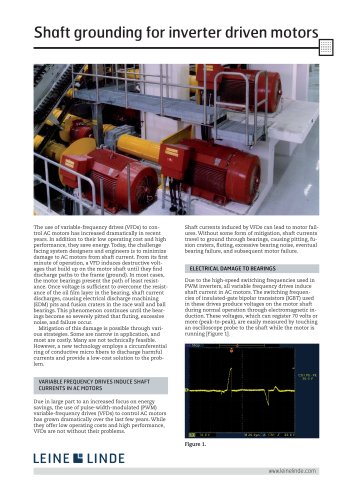
www.leinelinde.com Figure 1. VARIABLE FREQUENCY DRIVES INDUCE SHAFT CURRENTS IN AC MOTORS Shaft grounding for inverter driven motors The use of variable-frequency drives (VFDs) to control AC motors has increased dramatically in recent years. In addition to their low operating cost and high performance, they save energy. Today, the challenge facing system designers and engineers is to minimize damage to AC motors from shaft current. From its fi rst minute of operation, a VFD induces destructive voltages that build up on the motor shaft until they fi nd discharge paths to the frame (ground). In most cases, the motor bearings present the path of least resistance. Once voltage is suffi cient to overcome the resistance of the oil fi lm layer in the bearing, shaft current discharges, causing electrical discharge machining (EDM) pits and fusion craters in the race wall and ball bearings. This phenomenon continues until the bearings become so severely pitted that fl uting, excessive noise, and failure occur. Mitigation of this damage is possible through various strategies. Some are narrow in application, and most are costly. Many are not technically feasible. However, a new technology employs a circumferential ring of conductive micro fi bers to discharge harmful currents and provide a low-cost solution to the problem. Due in large part to an increased focus on energy savings, the use of pulse-width-modulated (PWM) variable-frequency drives (VFDs) to control AC motors has grown dramatically over the last few years. While they offer low operating costs and high performance, VFDs are not without their problems. Shaft currents induced by VFDs can lead to motor failures. Without some form of mitigation, shaft currents travel to ground through bearings, causing pitting, fusion craters, fl uting, excessive bearing noise, eventual bearing failure, and subsequent motor failure. Due to the high-speed switching frequencies used in PWM inverters, all variable frequency drives induce shaft current in AC motors. The switching frequencies of insulated-gate bipolar transistors (IGBT) used in these drives produce voltages on the motor shaft during normal operation through electromagnetic induction. These voltages, which can register 70 volts or more (peak-to-peak), are easily measured by touching an oscilloscope probe to the shaft while the motor is running [Figure 1]. ELECTRICAL DAMAGE TO BEARINGS
Open the catalog to page 1
www.leinelinde.com Shaft grounding for inverter driven motors STRATEGIES FOR MITIGATING SHAFT CURRENT DAMAGE Once these voltages reach a level suffi cient to overcome the dielectric properties of the grease in the bearings, they discharge along the path of least resistance typically the motor bearings to the motor housing. (Bearings are designed to operate with a very thin layer of oil between the rotating ball and the bearing race.) During virtually every VFD cycle, induced shaft voltage discharges from the motor shaft to the frame via the bearings, leaving a small fusion crater in the bearing...
Open the catalog to page 2
www.leinelinde.com Shaft grounding for inverter driven motors SHAFT CURRENT MITIGATION TECHNOLOGIES pass through the insulating layer and cause bearing failure. If attached equipment, such as a pump, provides this path, the other equipment often winds up with bearing damage of its own. Insulation and other bearing-isolation strategies can be costly to implement. Alternate discharge paths: When properly implemented, these strategies are preferable to insulation because they neutralize shaft current. Techniques range in cost and sometimes can only be applied selectively, depending on motor size...
Open the catalog to page 3
Leine & Linde AB T +46 (0)152-265 00 F +46 (0)152-265 05 Box 8, SE-645 21 Strängnäs, Sweden www.leinelinde.com [email protected] Shaft grounding for inverter driven motors About the author William Oh, General Manager of Electro Static Technology, 31 Winterbrook Road, Mechanic Falls, ME 04256 USA. Mr. Oh has extensive design and application experience in both automation and product development, specializing in passive dissipative technology for mitigating unwanted electrical currents. He has developed products and manufacturing equipment for several companies and is a member of the Illinois Tool...
Open the catalog to page 4All Leine & Linde catalogs and technical brochures
 300 Series
8 Pages
 2000 series
7 Pages
 1000 series
7 Pages
 Product Overview
15 Pages
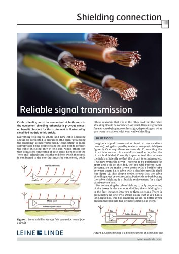 Shielding connection
4 Pages
 About encoders (general)
18 Pages
- Liebherr management software
- Liebherr automation software
- Liebherr rotary encoder
- Liebherr analysis software
- Measuring machine
- Liebherr incremental encoder
- Liebherr real-time software
- Liebherr cloud software
- Liebherr control software
- Liebherr incremental rotary encoder
- Liebherr monitoring software
- Flexible coupling
- Shaft shaft coupling
- Absolute rotary encoder
- Solid-shaft rotary encoder
- Optical rotary encoder
- Hollow-shaft rotary encoder
- Magnetic rotary encoder
- Industrial rotary encoder
- Liebherr limit switch