

Magnetic incremental encoders MIRC360 and 365

Magnetic incremental encoders MIRC360 and 365
- Impulses per rotation: 1 to 1024
- Resolution: Up to 4096 positions per revolution
- Supply voltage: +10 to +30 V for MIRC360, +5 ± 5% for MIRC365
- Supply current: 60 mA at 30V for MIRC360, 50 mA for MIRC365
- Output frequency: Max 200 kHz
- Output current: ± 25 mA for MIRC360, ± 20 mA for MIRC365
- Output type: HTL line driver (RS 422)
- Max rotational speed: 10000 min-1
- Max angular acceleration: 40000 rad.s-2
- Moment of inertia: 10 g.cm2 ± 10%
- Vibration: 10gn (10 to 2000 Hz)
- Shock: Max 50gn (100 ms)
- Shaft loads: Axial max 20 N, Radial max 40 N
- Working temperature: Standard -25˚ to +70˚C, Extended M -40˚ to +70˚C, Extended J -25˚ to +125˚C
- Humidity: Max 95% relative / 40 g.m-3 absolute
- Atmosphere: 73.3 to 126.6 kPa
- Protection: IP65
- Weight: Approx. 0.15 kg
- Cable length: Max 50 m
Catalog excerpts
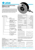
Magnetic incremental encoders MIRC360 and 365 MIRC36x - blind hollow shaft 6 mm The magnetic incremental rotary encoders MIRC360 and MIRC365 working on magnetic Hall Effect principle. The encoder converts rotary motion to electrical incremental signals. Mechanically is designed as blind hollow shaft and is mounted on the shaft cooperating devices. A typical use is in conjunction with digital control system or drivers for control of the electric motors. Note: Endoder MIRC36x can be delivered as absolute encoder. Mechanical data and working conditions Rotational speed max. Type identification MIRC3 6 X - X / XXXX X OUTLET PB - Cable 0,5 m radial (longer cable on request) NUMBER OF IMPULSES (PERIODS) PER ROTATION from 1 to 128 after one pulse, further 256, 512, 1024 with one zero impulse per rotation. DIAMETER OF SHAFTS 6 - shaft internal diameter 6 mm 5 - shaft internal diameter 5 mm 8 - shaft internal diameter 8 mm (other diameter on request) OUTLETS IDENTIFICATION Supply voltage Outlet 0 - +10 v +30 V HTL line driver 5 - + 5 V line driver MECHANICAL SPECIFICATION 6 - blind hollow shaft 6 mm TYPE OF ENCODER 3 - magnetic incremental encoder type MIRC36x ABZ differential incremental signals UVW differential commutation signals Number of incremental impulses (periods) per rotation: from 1 to 128 after one pulse, further 256, 512,1024 with one zero impulse per rotation. Technical data Resolution in positions = Number impulses per rotation (lines) x 4. P2 j |I f" ABZ incremental signals/period counter
Open the catalog to page 1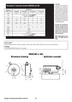
Description of connection elements MIRC360 and 365 Colors of connection cable Assembly The encoders MIRC360/ MIRC365 are mounted on a shaft of device by two screws in the encoder shaft. Rotational moment is captured by a pin dia. 5 mm placed in flange of device on pitch 20 mm. This pin shall be pushed into the groove in the encoder and leant against the groove side. The clearance is limited by a spring-loaded ball. Whereas the electrostatic sensitive components are used, the encoder must be connected without power supply and to follow the work rules for electrostatic sensitive devices. When temperature...
Open the catalog to page 2All LARM a.s. catalogs and technical brochures
 DRAW-WIRE ENCODER LS501
2 Pages
 Encoders
7 Pages
 JIGS & FIXTURES
3 Pages
 Company presentation
14 Pages


- Absolute rotary encoder
- Machining service
- Industrial rotary encoder
- Magnetic rotary encoder
- Machining
- Metal machining
- CNC machining
- Turning machining
- Automotive machining
- Standard rotary encoder
- Metal turning machining
- CNC turning machining
- 5-axis machining
- Stainless steel machining
- Plastic machining
- Steel machining
- Measuring gauge