Magnetic incremental encoders MIRC300, 305, 310, 315, 320 and 325
1 /2Pages

Magnetic incremental encoders MIRC300, 305, 310, 315, 320 and 325
1 /2Pages
Catalog excerpts
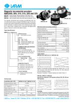
Magnetic incremental encoders MIRC300, 305, 310, 315, 320 and 325 MIRC30x – synchro flange, external diameter of the shaft 6 mm MIRC31x – clamping flange, external diameter of the shaft 10 mm MIRC32x – stator coupling, blind hollow shaft internal diameter 12 mm The magnetic incremental rotary encoders type MIRC300, 305, 310, 315, 320 and 325 working on magnetic Hall Effect principle. The encoder converts rotary motion to electrical incremental signals. Electrical signals provide information of bilateral position of two mechanical parts, angle turn or rotary motion. A typical use is in conjunction with digital control system or drivers for control of the electric motors. MIRC320, 325 MIRC310, 315 Mechanical data and working conditions Type identification Moment of inertia of mechanical parts max. OPTION (example) P – Pinion sticked to the shaft OUTLET PA – Cable 1 m axial PB – Cable 1 m radial KA – Connector type CONTACT axial KB – Connector type CONTACT radial (longer cable on request) Number of impulses (periods) per rotation from 1 to 128 after one pulse, further 200, 250, 256, 400, 500, 512, 1024, 2048 with one zero impulse per rotation. OUTLETS IDENTIFICATION Supply voltage Outlet 0 – +10 ÷ +30 V HTL line driver 5 – + 5 V line driver DIAMETER OF SHAFTS 0 – external dia. of the shaft 6 mm 1 – external dia. of the shaft 10 mm 2 – internal dia. of the shaft 12 mm (other diameter on request) TYPE OF ENCODER 3 – magnetic incremental encoder type MIRC3xx Working temperature Humidity relative / absolute Atmosphere (without aggressive substances) Number of incremental impulses (periods) per rotation: from after 128 Number of incremental impulses (periods) per rotation: from 1 to 128 1 to one pulse, further 200, 250, 256, 400, 500, 200, 1024, 2048 with one zero impulse per 2048 with after one pulse, further 512, 250, 256, 400, 500, 512, 1024, rotation. Resolution in positions = Number impulses per rotation (lines) x 4. one zero impulse per rotation. MIRC305 MIRC315 MIRC325 only and into resolution (lines) x 4. Resolution in/ positions/ = Number impulses per rotation 1024 impulses Number of incremental impulses (periods) per rotation: from 1 to 128 after one pulse, further 200, 250, /256, 400, 500, MIRC3252048 with one zero impulse per rotation. MIRC305 MIRC315 / 512, 1024, Resolution in positions = Number impulses per rotation (lines) x 4. only and into resolution 1024 impulses (without 200, 250, 400 and 500MIRC305 / MIRC315 / MIRC325 only and into resolution 1024 impulses impulses) Technical data ELECTRICAL DATE / TYPE Impulses (periods) per rotation Resolution (positions per revolution) = impulses x 4 Output frequency max. FO (kHz) Output max. IO (mA) Output ASSEMBLY The MIRC30x encoder is installed into appropriate equipment using 3xM4 screws or a groove. The position of the shaft is explicitly determined by a fitted diameter of 50h7 mm. The MIRC31x encoders are installed using 3xM3 screws and the position of the shaft is explicitly determined by a diameter of 36f8. It is recommended to use appropriate Assembly homokinetic connections (see the catalogue sheet „Accessories“). The MIRC32x encoders ASSEMBLY are mounted on the shaft of the respective into appropriate equipment using 3xM4 a The The MIRC30x encoder is installed device and 2 imbus M4 screws. After the encoder MIRC30x encoder is installed into appropriate equipment using 3xM4 screws or groove. The position required position and determined of the fixed plate connection are is to be turned to the of the shaft is explicitly4xM3 screwsby a fitted diameter of 50h7 mm. to The screws The connection has to usingof the shaft isto avoid exceeding the maximum MIRC31x encoders are installed be 3xM3 screws explicitly determined by be tightened.or a groove. The positiondesigned so as and the position of the shaft is explicitly determined by 50h7. The to the shaft and recommended a fitted diameter of a diameter of 36f8. It is it is are installeduse appropriate using 3xM3 admissible radial or axial load appliedMIRC31x encodersnecessary to keep the connection homokinetic cable of the MIRC3xx encoder must be fastened so as MIRC32x encoders aligned. Theconnections (see the catalogue sheet „Accessories“). The to avoid stress on the continuedsplashing page it is on next encoder are mounted is own weight. respective device and with running or encoder by on the shaft of theIn wet environments 2 imbus M4 screws. After the water is to be turned not to position the MIRC3xx encoders with the fixed pointing upwards. recommended to the required position and 4xM3 screws of the shaft plate connection are to be tightened. the electrostatic sensitive components used it is recommended Considering The connection has to be designed so as to avoid exceeding the maximum to admissible radial or axial without power supply and to follow the work rules connect the encoder load applied to the shaft and it is necessary to keep the connection for aligned. The sensitive MIRC3xx electrostaticcable of thedevices. encoder must be fastened so as to avoid stress on the encoder by is own weight. In wet environments with running or splashing water it is
Open the catalog to page 1
Assembly -continued from previous page Dimensioned drawing MIRC300, 305 MIRC310, 315 screws and the position of the shaft is explicitly determined by a diameter of 36f8. It is recommended to use appropriate homokinetic coupling (see the catalogue sheet Accessories"). The encoder MIRC320 or MIRC325 with stationary coupling is installed on the shaft of appropriate equipment and tightened by two imbus screws M4. Afterwards the encoder is turned to the required position and the stationary coupling is fixed by two or four (optimal) screws M3. The connection has to be designed so as to avoid exceeding...
Open the catalog to page 2All LARM a.s. catalogs and technical brochures
 DRAW-WIRE ENCODER LS501
2 Pages
 Encoders
7 Pages
 JIGS & FIXTURES
3 Pages
 Company presentation
14 Pages


- Incremental rotary encoder
- Absolute rotary encoder
- Machining service
- Magnetic rotary encoder
- Industrial rotary encoder
- Machining
- Metal machining
- CNC machining
- Turning machining
- Automotive machining
- Standard rotary encoder
- Metal turning machining
- CNC turning machining
- 5-axis machining
- Stainless steel machining
- Steel machining
- Plastic machining
- Measuring gauge