

Incremental rotary encoders IRC330 – 335

Incremental rotary encoders IRC330 – 335
Incremental rotary encoders IRC330 – 335 are designed to convert rotational motion into electrical signals using photoelectric raster scanning. They are primarily used in industrial applications for precise measurement and control systems.
Working Conditions:
- Vibration: 10 gn (10 ÷ 2000 Hz)
- Shock Impulse: 50 gn (100 ms)
- Operating Temperature: Standard 0° ÷ +60°C, Model M –25° ÷ +60°C
- Humidity: Relative 95% max, Absolute 40 g.m-3 max
- Atmosphere: Free of aggressive substances
Output Signals:
Encoders provide two basic signals shifted by 90° electrical, one zero pulse, and their negations. Zero pulse is not guaranteed for frequencies above 100kHz.
Type Marking and Outlets:
- PA, PB: Cable 1 m, axial or side
- KA, KB: Connector CONTACT 20.10.10.AA, axial or radial
- KKA, KKB: Cable 1 m with connector CONTACT 20.10.50.AC, axial or radial
Mechanical Design:
Outer shaft 12 mm, customizable according to customer requirements.
Electrical Data:
- Supply Voltage: 10-30V for IRC 330-332, 5±5% for IRC 333-335
- Supply Current Max: 50/30V for IRC 330-332, 100 mA for IRC 333-335
- Output Frequency Max: 150 kHz for IRC 330, 100 kHz for others
- Output Max: ±25 mA for IRC 330, ±20 mA for IRC 335
Technical Data:
- Rotation Speed: 10000 min.-1
- Angular Acceleration: 40000 rad.s-2
- Shaft Load: Axial 40 N max, Radial 60 N max
- Protection Type: IP65
- Weight: Max 0.35 kg
Ordering Information:
Orders should specify the number of pieces, encoder type, number of impulses per revolution, outlet design, and any non-standard design requirements.
Assembly Instructions:
Encoders are mounted into the equipment shaft and secured with M8 x 5.5 mm screw thread. Proper alignment and securing with cement are recommended.
Connection Guidelines:
Ensure connections prevent exceeding maximum radial or axial shaft load. Avoid placing encoders with the shaft up in wet environments. Follow electrostatic sensitive equipment handling procedures.
Catalog excerpts

Incremental rotary encoders IRC330 - 335 IRC330 - 335 - outer shaft 012mm ended with screw thread M8 x 5,5mm. The shaft shape can be specified according to the customer' s requirements. Incremental rotary encoders IRC with LED as the light source in the standard industrial version transform rotating motion in electric signals by means of photoelectric raster scanning of two glass elements (stator and rotor). They are assigned to mediate electric information about the mutual position of two mechanic units, the angle turn or rotating motions. IRC encoders are used mostly in connection with number indications or control systems. They can be used also in other devices, where high preciseness and reliability of measuring is required. Type marking IRC x x / xxxx xx x SUBSTANDARD (example) M - frost resistant -25° to +60°C D - optical indication of reset pulse by means of LED (KB, PB) OUTLET PA - cable 1 m, axial PB - cable 1 m, side KA - connector CONTACT 20.10.10. AA, axial KB - connector CONTACT 20.10.10. AA, radial KKA - cable 1 m with connector CONTACT 20.10.50.AC, axial KKB - cable 1 m with connector CONTACT 20.10.50.AC, radial NUMBER OF IMPULSES PER ROTATION 100, 200, 250, 360, 500, 512, 1000, 1024, 1250, 1500, 2048, 2500, 3600, 4096, 5000 and 6000 with one zero impulse per rotation. OUTLETS IDENTIFICATION Supply voltage Output MECHANICAL DESIGN OF SCHAFTS 3 - outer shaft 12 mm (which ends e.g. with M8x5,5 mm winding - shaft shape can be specified acc. to customer's requirements) TYPE OF ENCODER 3 - IRC3xx with LED as the light source Technical data Rotation Angular Inertia moment of mechanic parts Shaft load IRC - axial 330 - 335 - radial 330 - 335 Type of protection Weight max. Electrical data Working conditions Vibration acc. to FCCSN345791 Schock impulse 50 gn (100 ms) Operating temperature - standard - model M Humidity - relative - absolute Atmosphere free of aggressive substances.
Open the catalog to page 1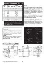
Note: Function Sensor is used with a supply resource enabling balancing the decrease of voltage on the cable as the feedback. If Sensor function is not used we recommend to connect PIN 2 to PIN 12 and PIN 10 to PIN 11. Assembly IRC330 - 335 encoders are placed into the shaft of the respective equipment and fastened by means of M8 x 5,5 mm screw thread on the encoder shaft, which must be secured by means of cement, e.g. AN 302 - 22 (the encoder is beared by 0 12 mm, the torsion moment is transmitted by means 60° cone). Hereafter the encoder shall be turned into the position required and fastened...
Open the catalog to page 2All LARM a.s. catalogs and technical brochures
 DRAW-WIRE ENCODER LS501
2 Pages
 Encoders
7 Pages
 JIGS & FIXTURES
3 Pages
 Company presentation
14 Pages


- Incremental encoder
- Absolute rotary encoder
- Machining service
- Industrial rotary encoder
- Magnetic rotary encoder
- Machining
- Metal machining
- CNC machining
- Turning machining
- Automotive machining
- Standard rotary encoder
- Metal turning machining
- CNC turning machining
- 5-axis machining
- Stainless steel machining
- Plastic machining
- Steel machining
- Measuring gauge