Catalog excerpts

Incremental rotary encoders IRC307, 317, 327 IRC307 – external diameter of the shaft ∅ 6 mm IRC317 – external diameter of the shaft ∅ 10 mm IRC327 – internal diameter of the shaft ∅ 12 mm The incremental rotary encoders IRC with LED diode as the light source in the standard industrial version convert the rotation to two elektrical sinusoidal incremental signals (1 and 2) with bilateral shift by 90° with approximate amplitude of 1 V pp and one zero impulse (3) per one rotation with approximate amplitude of 0,5 V. They are designed for transmission of electrical information on alignment of two mechanical units, their angle shift or rotational movements. The encoder IRC is mostly used together with digital indication or control systems. They may be used in other devices requiring high accuracy and reliability of measurement and transmission of signal over long distances. Type idenficatin IRC 3 x x / xxxx xx x SUBSTANDARD (example) P – Pinion ∅ 5 mm sticked to the shaft M – Frost resistant -25° ÷ +60°C D – Optical indication of zero impulse by a LED diode (KB, PB) H – Extended shaft, e. g. 35 mm T – Lowered moment of friction DESIGN OF OUTLETS PA – cable 1 m axial PB – cable 1 m side KA – conector CONTACT 20.10.10.AA axial KB – conector CONTACT 20.10.10.AA radial KKA – cable 1 m with conector CONTACT 20.10.50.AC axial KKB – cable 1 m with conector CONTACT 20.10.50.AC radial Technical data Rotations Angular acceleration Moment of inertia of mechanical parts Load of the IRC shaft – axial 307/317,327 – radial 307/317,327 Type of protection Weight Elektrical data Amplitude of the signal 1 and 2 0,6 ÷ 1,2 V pp (Zo = 120 Ω) Amplitude of the signal 3 0,2 ÷ 0,8 V (Zo = 120 Ω) The amplitude is understood to be the diferencial betwen sig+ and sig- of the particular signals Maximum frequency 180 kHz/-3 db Supply voltage 5V±5% Consumption of curent < 70 mA max. Maximum lenght of cable 150 m Working conditions Vibrations in accordance with FCČSN345791 Shock Operation temperature – standard – model M Humidity – relative – absolute Atmosphere without aggessive substances. Sequence of signals by turning right NUMBER OF IMPULSES PER ROTATION 512, 1024, 2048, 2500 with one zero impulse per rotation. OUTLET IDENTIFICATION Supply voltage Outlet 7 – +5 V ± 5 % sinus 1 V pp DIAMETER OF SHAFTS 0 – external diameter of the shaft 6 mm 1 – external diameter of the shaft 10 mm 2 – internal diameter of the shaft 12 mm Recommended connection of the input circuit of the coopeting device for one signal pair Input of signals from the sensor TYPE OF SWITCH 3 – IRC3xx with a LED as the light source
Open the catalog to page 1
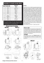
NOTE: The Sensor function is used in power supply sources allowing compensation of the voltage loss on cables as a feedback. In case the Sensor function is not used, it is recommended to conect pin 2 with pin 12 and pin 10 with pin 11 on the interconnecting cable. Assembly The IRC 307 encoder is installed into appropriate equipment using 3xM4 screws or a groove. The position of the shaft is explicity determined by a fitted diameter of 50h7 mm. The IRC 317 encoder are installed using 3xM3 screws and the position of the shaft is explicitly determined by a diameter of 36f8. It is recommended...
Open the catalog to page 2All LARM a.s. catalogs and technical brochures
-
DRAW-WIRE ENCODER LS501
2 Pages
-
Encoders
7 Pages
-
JIGS & FIXTURES
3 Pages
-
Company presentation
14 Pages


