

Incremental rotary encoders IRC300 – 325

Incremental rotary encoders IRC300 – 325
Catalog excerpts
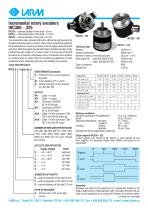
Incremental rotary encoders IRC300 - 325 IRC30x - external diameter of the shaft 0 6 mm IRC31x - external diameter of the shaft 010 mm IRC32x - internal diameter of the shaft 0 12 mm The incremental rotary encoders IRC with a LED as the light source in the standard industrial version converts rotary motion to electrical signals by the photoelectronic scanning of rasters onto two glass elements [stator and rotor]. Electrical signals provide information of bilateral position of two mechanical parts, angle turn or rotary motion. Common use of the IRC encoders is in connection with display units or numerical control systems on machine tools or robots. They are excellent for application in other equipment where measuring accuracy and reliability are required. Technical data Rotation Angular acceleration Moment of inertia of mechanical parts Shaft loads IRC - axial 300-305/310-325 - radial 300-305/310-325 Type identification IRC3 x x / xxxx xx x SUBSTANDARD (example) P - Pinion 0 5 mm or 8 mm sticked to the shaft M - Frost resistant -25° to +60°C D - Optical indication of zero impulse by LED (KB, PB) OUTLET PA - Cable 1 m axial PB - Cable 1 m radial KA - Connector CONTACT 20.10.10.AA axial KB - Connector CONTACT 20.10.10.AA radial KKA - Cable 1 m with connector CONTACT 20.10.50.AC axial or eq. KKB - Cable 1 m with connector CONTACT 20.10.50.AC radial NUMBER OF IMPULSES PER ROTATION 100, 200, 250, 360, 500, 512, 1000, 1024, 1250, 1500, 2048, 2500, 3600, 4096, 5000 and 6000 with one zero impulse per rotation. OUTLETS IDENTIFICATION Supply voltage 0 - +10 t +30 V 1 - + 10 t +30 V 2 - +10 t +30 V 3 - + 5 V 4 - + 5 V 5 - + 5 V DIAMETER OF SHAFTS 0 - external diameter of the shaft 6 mm 1 - external diameter of the shaft 10 mm 2 - internal diameter of the shaft 12 mm TYPE OF ENCODER 3 - IRC3xx with a LED as the light source Elektrical data Working conditions Vibration according to FCCSN345791 Shock Operating temperature - standard - model M Humidity - relative - absolute Atmosphere without aggressive substances. Output signals IRC300 - 325 2 basic signals (1,2) moved by 90° electric, 1 zero impulse (3) and their negation. For frequecies higher than 100kHz zero pulse is not quaranteed. Outlet push/pull OC NPN OC PNP OC NPN OC PNP line driver Assembly Encoders are fixed into the equipment by 3 screws M4. Position of the shaft is determined by fitted diameter 50h7. Encoders IRC310-315 are fixed into the equipment by 3 screws M3. Position of the shaft is deter-continued on next page
Open the catalog to page 1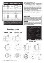
Description of connection elements IRC300 * 325 Note: Function Sensor is used with a supply resource enabling balancing the decrease of voltage on the cable as the feedback. If Sensor function is not used we recommend to connect PIN 2 to PIN 12 and PIN 10 to PIN 11. Assembly - continued from previous page mined by fitted diameter 36f8. Encoders IRC320-325 are installed on the shaft of the appropriate equipment and tightened with 2 imbus screws M4. Afterwards the encoder is turned to the required position and 4 screws M3 are tightened with stationary couplings. The connection has to be constructed...
Open the catalog to page 2All LARM a.s. catalogs and technical brochures
 DRAW-WIRE ENCODER LS501
2 Pages
 Encoders
7 Pages
 JIGS & FIXTURES
3 Pages
 Company presentation
14 Pages


- Incremental encoder
- Absolute rotary encoder
- Machining service
- Industrial rotary encoder
- Magnetic rotary encoder
- Machining
- Metal machining
- CNC machining
- Turning machining
- Automotive machining
- Standard rotary encoder
- Metal turning machining
- CNC turning machining
- 5-axis machining
- Stainless steel machining
- Steel machining
- Plastic machining
- Measuring gauge