Absolute rotary encoders ARC400 – 425
1 /2Pages

Absolute rotary encoders ARC400 – 425
1 /2Pages
Catalog excerpts

UIR/M Absolute rotary encoders ARC400 - 425 ARC400 - 425 are absolute one-revolution rotating encoders with a standard industrial design on a diameter of 58 mm and distinction of up to 2. It transforms the angle of turning to the corresponding electronic digital information in the Gray's code and in the number of bits established by the distinction by means of photoelectrical scanning of two rasters (rotor and stator). Absolute encoders do not lose information about the position even at the time when they are not energized. Outlet bits are brought out in parallel to individual pins of a connector or cable conductor. Absolute encoders are destined for intermediation of electric information about the mutual position of two mechanical parts or about rotation movements (speed, acceleration, number of rotations and the angle of turning). At customer’s request it is possible to bring out in the connector an error message informing about the function of the illuminant. When the distinction is 213, a phase-shifted incremental signal with a distinction of 2048 impulses per rotation (without negation) is also brought out to the thirteen bit. For distinction 210 a 12-pin connector is used, for higher distinctions a 16-pin connector is used, and for special designs up to 19 pin-ones are used. Type indication ARC 4 x x / xx xx OUTLET PA - cable 1m long,axial PB - cable 1 m long, radial KA - connector CONTACT- 20.10.10.AA ■— axial (number of pins 12 or 16) depends on number of bits KB - connector CONTACT- 20.10.10.AA radial (number of pins 12 or 16) depends on number of bits NUMBER OF BITS (number of states per revolution) 10 - 10 bits (210 = 1024 steps) 12 - 12 bits (212 = 4096 steps) 13 - 13 bits (213 = 8192 steps) DESIGN OF ELECTRICAL OUTPUTS Supply Voltage Output MECHANICAL DESIGN 0 - external shaft diameter 6 mm 1 - external shaft diameter 10 mm 2 - internal shaft diameter 12 mm Elektrical data and output signals level Sequence of signals ARC 213 model at clockwise rotation. Note: signals 24 to 210 are not shown. signals 211212 213, are not in proportion to the other signals.
Open the catalog to page 1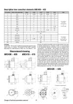
Assembly The ARC400 - 405 encoder is installed into appropriate equipment using 3xM4 screws or a groove. The position of the shaft is explicity determined by a fitted diameter of 50h7 mm. The ARC410 - 415 Dimensioned drawing ARC400 - 405 ARC410 - 415 encoder are installed using 3xM3 screws and the position of the shaft is explicitly determined by a diameter of 36f8. It is recommended to use appropriate hokinetic connections (see the cataloque sheet „Accessories“). The ARC420 - 425 encoder are mounted on the shaft of the respective device and 2 imbus M4 screws. After the that encoder is to be...
Open the catalog to page 2All LARM a.s. catalogs and technical brochures
 DRAW-WIRE ENCODER LS501
2 Pages
 Encoders
7 Pages
 JIGS & FIXTURES
3 Pages
 Company presentation
14 Pages


- Incremental encoder
- Incremental rotary encoder
- Absolute rotary encoder
- Machining service
- Magnetic rotary encoder
- Industrial rotary encoder
- Machining
- Metal machining
- CNC machining
- Turning machining
- Automotive machining
- Standard rotary encoder
- Metal turning machining
- CNC turning machining
- 5-axis machining
- Stainless steel machining
- Steel machining
- Plastic machining
- Measuring gauge