

Technical Data Mass Flow Measurement Grid

Technical Data Mass Flow Measurement Grid
- Circular Design: Inside duct length of 100 mm, wall thickness of 2-3 mm, optional flange according to EN 12220.
- Rectangular Design: Flanged at the duct, pneumatic connection on the side marked by air duct height.
- Suitable for gaseous media with known density.
- System pressure range: -0.5 to +0.5 bar.
- Standard repetition accuracy: ≤ ±1% of measurement value.
- Calibrated grids accuracy: ≤ ±1% on test bench, ≤ ±2% on site.
- Calculated grids accuracy: ≤ ±5% of measurement value.
- Circular Grids: Available in sizes from Ø 300 mm to Ø 1600 mm, with or without flange.
- Rectangular Grids: Available in various height and width combinations, with custom sizes available upon request.
Catalog excerpts

Technical Data Mass Flow Measurement Grid Fig. 1-1 Example of mass flow measurement grid in circular de- Fig. 1-2 Example of mass flow measurement grid in rectangular design with flange sign with flange Fig. 1-3 Dimensional drawing of circular version (front/side view) Fig. 1-4 Dimensional drawing of rectangular version (front/side view) Connecting pipe Welded cutting ring fitting G1/4" Measuring tube Measuring tube Nominal diameter (
Open the catalog to page 1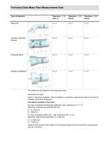
The tolerances are based on the measuring value Calculation formular: Inlet E = Tolerance multiplier ’ Type of obstacle x mass flow measurement grid 0 (circular) or diameter (square or rectagular) Calculation example of the Inlet For type of obstacle ’Rectangular deflection’ with a tolerance of +/- 1 %; Mass flow measurement grid DN 300 mm E = 6 x 300 mm E = 1800 mm For type of obstacle ’Elbow 30 °’ with a tolerance ofz +/- 3 %; Mass floe measurement grid 800 mm x 300 mm E = 2 x 854 mm E = 1708 mm Outlet A shall consist of the length of the diameter/diagonal of the mass flow measurement grid...
Open the catalog to page 3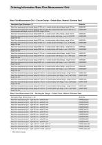
other sizes on reques
Open the catalog to page 4
The information in this publication is subject to technical changes. LAMTEC Meft- und Regeltechnik fur Feuerungen GmbH & Co. KG WiesenstralJe 6 D-69190 Walldorf Phone: +49 (0) 6227 / 6052-0 Fax: +49 (0) 6227 / 6052-57 e-mail:[email protected] www.lamtec.de Presented by: Print no. DLT8000-15-aEN-020 Printed in Germany
Open the catalog to page 5All Lamtec catalogs and technical brochures
 F130I
F130I4 Pages
 ETAMATIC
7 Pages
 KS1D-HT
7 Pages
 KS1D-Ex
3 Pages
 KS1D without Housing
4 Pages
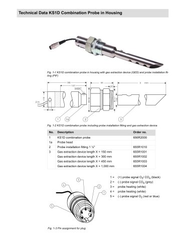 KS1D in Housing
5 Pages
 KS1 without housing
4 Pages
 High Dust Mounting Flange
2 Pages
 BT300
BT3005 Pages
 GKI300
3 Pages
 BurnerControl FA1
4 Pages


- Touch monitor
- LCD screen
- Panel-mount screen
- Valve actuator
- Interface software
- Rotary valve actuator
- Simulation software solution
- Electric valve actuator
- Gas burner
- 10" monitor
- Natural gas burner
- Monitoring control system
- Production monitoring system
- Process control system
- Indirect fired burner
- Flame detector
- Gas probe
- IR flame detector
- UV flame detector
- Pilot burner