
- Catalogs
- LAIRD TECHNOLOGIES
- LT-THR-THIN FILM THERMOELEC 1212


LT-THR-THIN FILM THERMOELEC 1212

LT-THR-THIN FILM THERMOELEC 1212
Thin Film Thermoelectric Modules (TEMs) are solid-state devices that use the Peltier effect for heat management in electronic systems. They are crucial for preventing system failures as electronic components become smaller and generate more heat.
Thin film TEMs are much thinner than traditional bulk TEMs, allowing for higher heat flux (100 to 400W/cm²) and efficiency. They offer rapid thermal response times for precise temperature control.
The performance of TEMs is depicted by a load line on a performance chart, indicating the maximum power and temperature difference they can handle, which is essential for understanding their cooling capacity.
Integrating TEMs into systems alters the thermal profile, providing a net cooling benefit. Effective thermal pathways are crucial, especially in high-density packages.
Designing thermal management systems involves understanding heat flow and incorporating solutions early. Passive cooling methods include thermal interface materials, heat spreaders, and heat exchangers.
As devices shrink, active cooling solutions like TEMs are necessary for efficient heat management, targeting specific hot spots to reduce overall cooling requirements.
TEMs consume power but can be more efficient than passive components if used strategically, focusing on localized cooling to minimize system-level heat dissipation.
TEMs provide precise thermal management by cooling necessary areas, optimizing system efficiency. The coefficient of performance (COP) measures their efficiency, and careful integration is needed to enhance performance.
Thin film TEMs are compact, requiring precise handling. Assembly involves soldering to a heat rejection surface, using mechanical spacers, and liquid metals for optimal thermal interfaces, considering thermal expansion and mechanical isolation.
Materials include solders, fluxes, liquid metals, and mechanical supports. Precision tools are recommended for handling and assembly.
The procedure includes soldering the TEM, attaching spacers, coating headers with liquid metal, and securing the surface, focusing on minimizing thermal resistance and mechanical stress.
Handling requires precision tools, and premium materials should be used for thermal interfaces. Soldering guidelines emphasize thin bond-lines to reduce thermal resistance.
Temperature sensing is crucial for precise thermal management. Micro-scale thermistors are preferred for their sensitivity and ease of integration.
The eTEC™ Series modules are validated for reliability under demanding conditions, adhering to Telcordia’s GR468-CORE specification, suitable for optoelectronic applications.
Mechanical shock tests showed compliance with standards, indicating robust mechanical integrity.
High-temperature storage tests demonstrated long-term reliability and stability under extreme conditions.
Power cycling tests showed minimal changes in performance, surpassing GR-468 standards, indicating high reliability under extreme usage.
Catalog excerpts
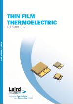
THIN FILM Innovative Technology
Open the catalog to page 1
Innovative Technology THR-UM-THIN FILM THERMOELECTRIC 1212 Any information furnished by Laird Technologies, Inc. and its agents is believed to be accurate and reliable. All specifications are subject to change without notice. Responsibility for the use and application of Laird Technologies materials rests with the end user. Laird Technologies makes no warranties as to the fitness, merchantability, suitability or non-infringement of any Laird Technologies materials or products for any specific or general uses. Laird Technologies shall not be liable for incidental or consequential damages of any...
Open the catalog to page 2
Revision History Revision 1 Description 8/30/2012 – Initial Version Laird Technologies
Open the catalog to page 3
Thin Film Thermoelectrics As components, packages and systems continue to shrink in size, the heat generated in these dense electronic systems can be quite large and can lead to a significant rise in temperatures that in turn can cause device and system-level failures. Heat has always been an issue for system designers, but only recently has the problem become so severe that thermal management solutions can no longer be introduced as an afterthought. Thermal management must be considered from the beginning of the design process in order to avoid causing severe problems at the system level. This...
Open the catalog to page 4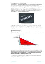
Advantages of Thin Film Technology Conversely, thin film thermoelectrics target the source of the heat flux to provide thermal management and control. These embeddable TEMs use semiconductor processing techniques to create a nano-structured thin film used for the P and N legs. Thin film TEMs are typically 5 to 20µm thick, versus 200µm for conventional bulk TEMs, resulting in several differences. The heat flux, which is inversely proportional to the thickness of the thermoelectric material, is more than 20 times greater than bulk TEMs. Thin film TEMs can also pump a maximum heat flux of 100 to...
Open the catalog to page 5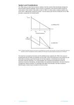
System Level Considerations The TEM, being an active thermal device, creates a thermal inversion that dramatically changes the thermal profile inside the package. Figure 3 shows a comparison of the thermal profile through the cross section of the module in two cases, a) with no TEM, or in other words, a passive solution only, and b) with a TEM actively cooling the junction. It can be clearly seen that the introduction of the TEM provides a substantial net cooling benefit. Figure 3: Temperature profiles through the cross section of a package from the junction to the case (θJC), and case to ambient...
Open the catalog to page 6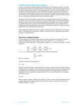
Thin Film Thermal Management Design In order to understand the design challenges facing engineers in the electronics industry, we need to first look at the way heat moves or flows through a material system, and to do this we need to look at the forces that govern that movement. Heat has always been an issue for system designers, but only recently has the problem become so severe that thermal management solutions can no longer be introduced as an afterthought. Heat flux must be looked at from the beginning of the design process. Heat flowing through a material will always create a temperature...
Open the catalog to page 7
Passive Cooling The primary systems used for passive cooling of electronic and optoelectronic systems are materials configured as thermal interface materials (TIM), heat spreaders and heat exchangers. Each perform a different function for removing heat from a system. Heat exchangers may be an environment (e.g. liquid or air) or object that absorbs and then dissipates heat while in physical or thermal contact. This may occur in different ways including direct and radiant transfer of heat. A heat exchanger’s performance is a function of material, geometry, and the overall surface heat transfer...
Open the catalog to page 8
An active thermal management device, such as a thermoelectric module (TEM), has been employed to provide this additional heat pumping and temperature stabilization capability. A simple example of the type of heat pumping and temperature control offered by a TEM and its ability to cool a device is shown in Figure 5. Figure 5: TD is the temperature of the device to be cooled; TC is the temperature of the cold side of the TEM; TH is the temperature of the hot side of the TEM; and TA is the temperature of the ambient or surrounding environment where the heat is to be dumped. A Comparison of Active...
Open the catalog to page 9
This can be illustrated by looking at the coefficient of performance (COP) of a TEM, which is defined as: COP = A TEM will pump a certain amount of heat, Q, and add an additional amount of heat, Q*COP to move this heat. This is a result of the inherent inefficiency in all engines. As a result, bulk TEMs are often sold as systems that include the TEM and a heat transfer mechanism such as a fan and heat sink or liquid heat exchanger. The value of the TEM in this case is that it can deliver sub-ambient temperatures and provide active temperature control but at the cost of increasing the system level...
Open the catalog to page 10
Module Handling and Assembly 2 Thin film thermoelectric modules have extremely small form factors with footprints smaller than 10 mm . These devices are only 0.6mm high, making them the thinnest thermoelectric modules available on the market today. Due to their small form factor, care must be taken when handling and assembling modules into sub-assemblies for validation testing and production use. Figure 6 shows a typical thin film thermoelectric module. Please note the location of the primary and secondary headers, which are referenced in the assembly instructions that follow. Figure 6: Typical...
Open the catalog to page 11
The assembly procedure that follows describes a method for fabricating a thermoelectric assembly as shown in the figure above where a thin film thermoelectric device is packaged between thermally conductive plates. These plates could represent separate heat-spreaders or could be an integral part of the heat-exchangers or temperature controlled target. The package has been optimized to meet the conflicting requirements of highly conductive thermal interfaces while allowing for mechanical isolation TM of the eTEC . Suggested Parts and Supplies List Solder – available from Indium Corporation in...
Open the catalog to page 12All LAIRD TECHNOLOGIES catalogs and technical brochures
 Board Level Shields Catalog
26 Pages
 EMI-CAT-Essentials 1213
117 Pages
 THR-UM-PC-24-TS-58
16 Pages
 THR-UM-AA-230
8 Pages
 THR-BRO-Thermal
19 Pages
 YS3805
1 Page
 YF45018
2 Pages
 YF880012
2 Pages
 YF88008
2 Pages
 YF450112
2 Pages
 ANT-DS-POE-xxi 0612
2 Pages
 ANT-DS-POE-XXS-AFI 0712
2 Pages
 LWS-BRO-Devices 1212
6 Pages
 IAS-DS-External GPS 0115
2 Pages
 TEL-DS-Internal GPS 0310
2 Pages
 THR-DS-TC-NTC-2 0413
2 Pages
 THR-DS-GAPFILLER 0710
2 Pages
 THR-DS-UT9,28,F2,4040
2 Pages
 Laird_Thermoelectric_Module
8 Pages
 THR-BRO-LCS-012515
6 Pages
 Power-Over-Ethernet
2 Pages
 SIAMnet
12 Pages
 BL620 Series
2 Pages
 Multi-band Survivor ?
2 Pages
 Liquid Cooling Systems
6 Pages
 Ferrite EMI Noise Filtering
8 Pages
 EMI CATALOG
116 Pages
 Board Level Shields and Contacts
26 Pages
 AC4486 - 868MHz Radio Module
3 Pages
 Client Side Antennas
2 Pages
 RFID Antennas
18 Pages
 Ferrite EMI Cable Cores
24 Pages
 WLAN Antennas
44 Pages
 GPS/Telematics
8 Pages
 Thermal Management Solutions
96 Pages
 Knitted Conductive EMI Gasket
36 Pages
 EMI ESSENTIALS
36 Pages


Archived catalogs
 EMI Capabilities
13 Pages
 ZB2430 Wireless Modules
3 Pages


- Temperature probe
- Waterproof temperature sensor
- Industrial gateway
- Humidity and temperature probe
- Ethernet gateway
- Serial gateway
- Relative humidity and temperature sensor
- Radio antenna
- Wireless gateway
- DIN rail gateway
- IoT gateway
- Wireless module
- Omnidirectional antenna
- Waterproof humidity and temperature sensor
- Digital humidity and temperature sensor
- PCB
- Analog humidity and temperature sensor
- GNSS antenna
- USB gateway
- Compact gateway