- Catalogs
- Kyowa Electronic Instruments Co.
- STRAIN GAGES
STRAIN GAGES
1 /100Pages

STRAIN GAGES
1 /100Pages
Catalog excerpts

Move into the future with reliable measurements STRAIN GAGES
Open the catalog to page 1
Wide range of applications and easy handling— essential factors for choosing KYOWA strain gages Strain gages are designed to electrically detect "strain," minute mechanical changes occurring in response to applied force. They are used not only for machines and moving objects but also in various fields including electrical equipment, civil engineer- ing, building construction, chemicals and medicine. Strain gages enable detection of imperceptible elongations or shrinkages occurring in structures. Measurement of such elongations or shrinkages reveals the stress applied to the structure. Stress...
Open the catalog to page 3
■Unknown physical quantities such as load, pressure and ■Strain Gages • Gages for General Stress Measurement • Waterproof Foil Strain Gages • Strain Gages for Concrete • Gages for Composite Materia Is/Plastics 2 KYOWA STRAIN GAGES
Open the catalog to page 4
Gages for Low-elasticity Materials i Semiconductor Strain Gages for Ultra-small Strain Measurement High-elongation Gages ► Foil Strain Gage for Hydrogen Gas Environment ► Bending-strain Measuring Gages > Gages with Protector Embeddable Gage Special Gages KYOWA STRAIN GAGES 3
Open the catalog to page 5
■ Strain Gage Model Number Coding System ©Series Designation - (D Resistance © Gage Pattern \(D Applicable Linear Expansion Coefficient General-purpose foil strain gage Foil strain gage with temp, sensor Foil strain gage Waterproof foil strain gage Small waterproof foil strain gage Weldable waterproof foil strain gage Wire strain gage Embedded foil strain gage for concrete Embedded wire strain gage for concrete Foil strain gage for composite materials Foil strain gage for printed boards Foil strain gage for plastics Foil strain gage for low-elasticity materials Semiconductor strain gage semiconductor...
Open the catalog to page 6
KYOWA can customize strain gages according to measuring purposes. © Length of Leadwire Cable Leadwire Cable Leadwire Cable 1: CFRP, etc. for composite materials 3: GFRP, etc. for composite materials 5: GFRP, etc. for composite materials 6: GFRP, etc. for composite materials 9: CFRP, GFRP, etc for composite materials 13: NCF, etc. forcorrosion and heat-resistant alloys Composite material GFRP (35.0) KHCX, KHCR, KHCV gages) copper wires high/low temp. temp, low-noise copper wire cable encapsulated gage Number: Length of soft cable V: With bridge adapter F: With compression fitting FV: With both...
Open the catalog to page 7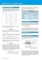
■ How strain gages work Strain, Stress, and Poisson's Ratio When a material receives a tensile force P, it has a stress s that corresponds to the applied force. In proportion to the stress, the cross section contracts and the length elongates by AL from the length L the material had before receiving the tensile force (see upper illustration in Fig. 1). Principle of Strain Gages Each metal has its specific resistance. An external tensile force (compressive force) increases (decreases) the resistance by elongating (contracting) it. Suppose the original resistance is R and a strain-initiated change...
Open the catalog to page 8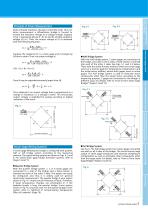
Principle of Strain Measurement Strain-initiated resistance change is extremely small. Thus, for strain measurement a Wheatstone bridge is formed to convert the resistance change to a voltage change. Suppose voltage (V) is E. Then, the output voltage eo (V) is obtained with the following equation: Suppose the resistance R1 is a strain gage and it changes by AR due to strain. Then, the output voltage is. Since R may be regarded extremely larger than AR, Thus obtained is an output voltage that is proportional to a change in resistance, i.e. a change in strain. This microscopic output voltage is...
Open the catalog to page 9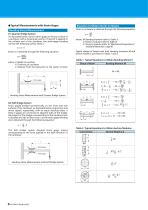
• Typical Measurements with Strain Gages Bending Stress Measurement (1) Quarter Bridge System As illustrated below, bond a strain gage on the top surface of a cantilever with a rectangular section. If load W is applied to the unfixed end of the cantilever, the strain-gage bonding site has the following surface stress o: Strain EO is obtained through the following equation: where, b: Width of cantilver L: Distance from the load point to the center of strain - Strain gage Bending Stress Measurement with Quarter Bridge System (2) Half Bridge System Strain gages bonded symmetrically on the front...
Open the catalog to page 10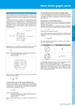
How strain gages work Torsional and Shearing Stress Measurement of Axis When twisted, an axis has shearing stress x, and in the 2 directions inclined by 45° from the axial line it has tensile and compressive stress in an equal magnitude to the shearing In measuring strain on a twisted axis under simple shearing stress status, the strain gage does not directly measure the shearing strain but detects tensile or compressive strain initiated by tensile or compressive stress that is simultaneously generated with the shearing stress. Stress conditions on a microscopic part of the surface of the axis...
Open the catalog to page 11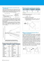
•Principle of Self-temperature-compensation Gages (SELCOM Gages) Suppose the measuring object and the resistive element of the strain gage have linear expansion coefficients (5s and |3g, respectively. Then, the strain gage bonded on the surface of the object provides a thermally-induced apparent strain ET per 1°C that is expressed with the following equation: •Temperature Effect of Leadwire with 2-wire System a: Resistive temperature coefficient Ks: Gage factor of strain gage The self-temperature-compensation gage is designed so that ET in the above equation is approximated to zero by controlling...
Open the catalog to page 12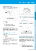
How strain gages work •Influence of Insulation Resistance The insulation resistance of a strain gage including leads does not affect the measured value if it is higher than 100 MQ. But if the insulation resistance changes drastically during measure- ment, it causes the measured value to include an error. Insulation resistance Strain gage Bridge Circuit Designed with Insulation Resistance Taken into Consideration If the insulation resistance descends from n to n. in the figure above, error strain e is: Rg = 120 Q (resistance of strain gage) Ks = 2.00 (gage factor of strain gage) n = 1000 MQ (original...
Open the catalog to page 13All Kyowa Electronic Instruments Co. catalogs and technical brochures
 DB-120V-4?DB-350V-4
2 Pages
 TPS-A
TPS-A2 Pages
 Load cells
88 Pages

- Force sensor
- Measuring device
- Data logger
- Tension/compression force transducer
- Strain gauge force sensor
- Acceleration sensor
- Pressure probe
- Signal amplifying integrated circuit
- USB datalogger
- Beam type force sensor
- Piezoelectric accelerometer
- Data-logger with screen
- Compression force transducer
- Portable gauge
- Displacement transducer
- Membrane pressure sensor
- Analog pressure sensor
- Linear displacement sensor
- Triaxial acceleration sensor
- Pressure transducer