
- Catalogs
- Kurt J Lesker
- Feedthroughs


- Products
- Catalogs
- News & Trends
- Exhibitions
Feedthroughs

Feedthroughs
This document provides a comprehensive overview of feedthroughs, which are devices used to transfer services, utilities, and signals through a vacuum wall. The main categories covered include electrical, gas and liquid, cryogen (LN2), and optical feedthroughs. However, viewports and motion devices are not included in this discussion.
Gas Discharges: The maximum voltage rating of a feedthrough is determined in air at one atmosphere pressure. Different gases have varying breakdown voltages (BVs), with simpler gases generally having lower BVs. Helium, for example, has a BV roughly half that of air.
Coaxial Cables: These cables have a center conductor insulated from a conducting outer shield, providing stable signal transmission and shielding against noise. The impedance, a key characteristic, is typically 50 ohms in vacuum applications.
These feedthroughs carry electricity through the vacuum wall to powered devices. They consist of conductors sealed to an insulator, which is then sealed to a flange or baseplate. Important selection criteria include maximum operating voltage, current per conductor, and environmental conditions.
Designed for transferring low-current, low- or high-voltage signals, these feedthroughs can be single-ended or double-ended. They are often coaxially shielded to protect against electrical noise. Key considerations include voltage, impedance, temperature range, and connector types.
These feedthroughs transfer temperature signals through the vacuum wall using thermocouples, which are two dissimilar metal wires. Selection factors include temperature range and the number of measurement locations.
Used to electrically isolate parts of a vacuum vessel while maintaining mechanical connection. They are available in various voltage ratings and configurations.
Similar to gas-liquid feedthroughs but designed to minimize heat transfer and cryogen evaporation.
Various connector and cabling options are available for electrical and thermocouple feedthroughs, including standard connectors and specialized vacuum accessories.
These deliver liquids or gases to vacuum-mounted devices, often for temperature maintenance or actuation. Selection involves matching flange and tube specifications to existing components.
The document includes charts explaining the part number system for cables, ceramic beads, discs, and breaks, detailing specifications and configurations.
The document provides detailed specifications for various types of feedthroughs used in high vacuum (HV) and ultra-high vacuum (UHV) applications. The primary materials used include stainless steel for conductors and alumina for insulators. The feedthroughs are designed to handle maximum voltages ranging from 500 VDC to 7,500 VDC and a maximum current of 3A. They are suitable for cryogenic temperatures and have specific temperature ranges depending on the type of connection.
1. KF (QF) Flange, Double-Ended: These are available in grounded and floating shield configurations, with voltage ratings of 500 VDC for grounded and 2,500 VDC for floating shields. They are designed for use with RG-58U cables and bayonet connections.
2. CF Flange, Single-Ended: These feedthroughs can handle up to 5,000 VDC for grounded shields and 2,500 VDC for floating shields. They are compatible with RG-59U cables and are suitable for temperatures from -200º C to +450º C.
3. SHV-B Coaxial Connectors: These connectors feature grounded shields and are bakeable up to 450º C. They are designed for high-temperature applications and have a maximum voltage rating of 7,500 VDC.
- The feedthroughs are constructed from vacuum-grade materials, ensuring reliability in HV and UHV environments.
- They are designed to prevent crossmating with BNC or MHV components, enhancing safety and compatibility.
- The document advises against crossmating MHV feedthroughs with BNC feedthroughs due to different voltage ratings.
These feedthroughs are suitable for a variety of applications requiring high voltage and high vacuum conditions. They are particularly useful in environments where maintaining operational integrity at extreme temperatures is critical.
The document references additional resources for connectors and cabling, indicating where to find compatible coaxial connectors and cables.
- Voltage and Current Ratings: The feedthroughs support maximum voltages ranging from 500 VDC to 20,000 VDC and currents up to 15A, depending on the model.
- Materials: Nickel is used as the conductor material, with alumina as the insulator. The construction includes vacuum-grade materials like 304 stainless steel and high-purity alumina ceramic insulation.
- Temperature Range: The operational temperature ranges from -200º C to +450º C for weld adapters and CF flanges, with a maximum ramp rate of 25º C/minute.
- Connection Types: Bayonet and screw thread connections are available, with air-side cable connectors and optional vacuum-side push-on connectors.
- SHV-5 and SHV-10: These are designed for high voltage applications with grounded shields and recessed female contacts to prevent electrical shock.
- SHV-20: Offers the highest voltage and current ratings, featuring grounded shields and recessed or exposed ceramic insulators.
- Type N: Suitable for lower voltage applications (500 VDC), using screw thread connections.
- Material and Construction: Most feedthroughs are constructed using nickel or stainless steel conductors with alumina insulators. The shields can be grounded or floating, depending on the application.
- Voltage and Current Ratings: The maximum voltage ranges from 500 VDC to 2500 VDC, with current ratings typically at 1A or 3A depending on the type of feedthrough.
- Temperature and Vacuum Applications: These feedthroughs are suitable for high vacuum (HV) or ultra-high vacuum (UHV) applications, with temperature ranges from -270°C to +450°C for different components.
- Connection Types: Connections are typically screw thread or bayonet, with specific configurations for air-side and vacuum-side connectors.
- Type N: Includes single-ended and double-ended configurations with CF and KF flanges, suitable for high voltage and current applications.
- SMA and SMB Feedthroughs: These are subminiature coaxial feedthroughs with options for floating or grounded shields, designed for specific impedance matching and high-frequency applications.
- BNC to Microdot: These feedthroughs adapt coaxial connection styles, typically used in deposition monitors.
- MPC Multi-Pin Circular: Available in configurations with multiple pins, these feedthroughs are non-magnetic and UHV compatible, featuring gold-plated stainless steel pins.
- Compatibility: Ensure compatibility with existing systems, especially in terms of flange size and connection type.
- Environmental Conditions: Consider the temperature and vacuum conditions of the application to select the appropriate feedthrough type.
- Impedance Matching: For high-frequency applications, impedance matching is crucial to minimize signal loss.
- Multi-Pin Circular Connectors: Available in configurations ranging from 3 to 41 pins, these connectors are gold-plated stainless steel with a voltage rating of 1kV DC and a current capacity of 5A per pin. They are available with crimp or solder options and various flange sizes.
- MPDT Sub D-Type Feedthroughs: These are available in pin densities from 9 to 50 pins, with a maximum voltage of 500 VDC and a current capacity of 5A per pin. They feature PEEK insulators and are suitable for HV or UHV applications.
- Subminiature-C Multipin Feedthroughs: Designed for UHV applications, these feedthroughs support a 9-pin configuration, are rated for 250°C, and are available with CF and QF flange mounts.
- MS Multi-Pin Feedthroughs: These are available in single-ended and double-ended versions, with configurations ranging from 4 to 35 pins. They are made from Alumel or Molybdenum, with a voltage rating of 700V DC and a current capacity of 10A per pin.
- It is recommended not to purchase weldable versions of feedthroughs unless equipped with the necessary tools and skills.
- Refer to the Connectors & Cabling section for additional components such as mil-spec connectors, inline barrel connectors, and coaxial cables.
- Each table provides detailed dimensions for various connector configurations, including pin count, material, voltage, current capacity, and part numbers.
- Pricing is indicated as 'Call,' suggesting that prices are available upon request.
- Type E Mini Plug: Available in weldable, CF flange, KF (QF) flange, and NPT (M) single-ended configurations. They support 1 to 5 pairs of thermocouples, with positive wires made of Chromel® and negative wires made of Constantan. The temperature range is -200º C to +900º C.
- Type E Mil-Spec Plug: Available in CF flange, KF (QF) flange, and NPT (M) terminations, supporting 2 to 10 pairs. They also use Chromel® and Constantan wires, with the same temperature range.
- Type E Push-On: Available in weldable, CF flange, and KF (QF) flange configurations, supporting 2 to 5 pairs. They maintain the same wire materials and temperature range.
- Type E Mini Plug Plus Power: These include additional power conductors made of copper or nickel, rated up to 5,000 volts and 30 amps, suitable for high vacuum and UHV applications.
- Constructed from vacuum-grade materials, including OFHC copper or nickel conductor pins, high-purity alumina ceramic insulation, and 304 stainless steel mounts.
- Assemblies come with miniature air-side thermocouple connectors and vacuum-side thermocouple lugs.
- Power leads are not supplied with connectors and must be purchased separately.
- Mil-Spec Connectors: These connectors are available in various configurations with different flange sizes and thermocouple (T/C) pairs. The document lists dimensions for each configuration, including air side and vacuum side measurements, and provides part numbers for ordering.
- Type J Mini Plug: Designed for high vacuum and ultra-high vacuum (UHV) applications, these connectors feature positive wires made of iron and negative wires of Constantan. They are available in single-ended and double-ended configurations with various flange sizes and T/C pairs.
- Type J Push-On: This section describes connectors with push-on pins, available in different flange sizes and T/C pairs. The document provides detailed dimensions and part numbers for each configuration.
- Type J Mini Plug Plus Power: These connectors combine thermocouple and power capabilities, featuring nickel or copper power conductors. They are rated for high voltage and current applications, suitable for environments requiring both power and temperature measurements.
- Flange Sizes: Various sizes including 1.33" CF, 2.75" CF, KF16, KF25, KF40, and ISO63.
- Thermocouple Pairs: Available in configurations ranging from 1 to 10 pairs.
- Materials: Connectors feature materials such as iron, Constantan, copper, and nickel for different applications.
- Temperature Range: Type J connectors are suitable for temperatures from 0º C to 750º C.
- Power Ratings: Power connectors are rated up to 5,000 volts and 30 amps per pin.
- Available in KF16 and KF40 sizes with different nickel coatings and dimensions.
- Refer to Connectors & Cabling for additional connector types and configurations.
- Type K: Designed for high vacuum and UHV applications, featuring Chromel® and Alumel® wires, with a temperature range from -200º C to 1,250º C. Available in various flange sizes and configurations.
- Type R: Suitable for high vacuum applications, using copper and alloy 11 wires, with a temperature range from 0º C to 1,450º C. Compatible with Type S thermocouples.
- Type T: Features copper and Constantan wires, with a temperature range from -200º C to 350º C. Includes stainless steel nuts and screws for attachment.
- Available in Type J, K, E, T, & N styles, with miniature air-side connectors and bendable metal sheaths made of stainless steel or Inconel®.
- Custom configurations available for probe numbers, types, and lengths.
- Detailed dimensions and part numbers are provided for each configuration, with options for custom lengths and materials.
- Refer to Connectors & Cabling for additional accessories and configurations.
This document provides detailed specifications and configurations for various types of feedthroughs used in vacuum and atmospheric applications. It includes matrices for CF (ConFlat) and KF (QF or NW) flanges, detailing the compatibility of different tube sizes and terminations on both vacuum and atmosphere sides.
These feedthroughs are designed for transferring gases and liquids through vacuum systems. The document provides a matrix to determine available configurations, including tube outer diameters and termination types such as Tube Ends (TE), VCR (male and female), VCO (male and female), and Swagelok.
Similar to gas/liquid feedthroughs, LN2 feedthroughs are specifically designed for liquid nitrogen applications. The document outlines the available configurations and part numbers for these feedthroughs, emphasizing the importance of selecting the correct flange and termination type.
Ceramic breaks are used for electrical insulation in high vacuum and ultra-high vacuum (UHV) applications. They are constructed with high-purity alumina ceramic insulation and are available in various voltage ratings and dimensions. The document lists specific part numbers and dimensions for different configurations.
This section covers connectors, including Mil-Spec multi-pin thermocouple connectors and thermocouple miniature connectors. These connectors are designed to meet military specifications and are available for various thermocouple types, including E, J, and K.
- Ensure compatibility of feedthroughs with the specific application requirements, including flange type, tube size, and termination type.
- Consider the voltage and material specifications for ceramic breaks to ensure proper insulation and performance in vacuum environments.
- Use the provided matrices to accurately build part numbers for ordering and configuration purposes.
These connectors are designed to fit MPC instrumentation feedthroughs and are compliant with military specifications. The MS-3106A models feature solid-shell, straight-threaded connectors with polarized keyways and silver-plated contacts with pre-tinned solder pockets. Connectors must be ordered separately from the MPC feedthroughs.
- Voltage: 500V to 1250V
- Amperage: 3.5A to 13.0A
- Pin sizes and configurations vary by model.
Available in bayonet, threaded, and snap-on styles, these connectors are rated from 500V to 20,000V and typically use PTFE as the dielectric material.
Made from beryllium copper, these connectors feature cross-screws for wire retention and are available in various sizes to accommodate different wire diameters.
Constructed with vacuum-grade materials, these cables are suitable for high temperatures and rated for high vacuum and UHV applications. They are available in 1/8" and 1/4" sizes with various termination styles.
Accessories for MPDT Sub D-Type Feedthroughs include various pin connectors and adapters, available in PEEK and ceramic materials.
These wires are designed for high vacuum and UHV applications, available in various materials such as copper, nickel, and stainless steel. They are sold in 12" increments and are suitable for extending thermocouple lengths.
Used as spacers to insulate multi-pin instrumentation and thermocouple feedthroughs, these ceramic components provide equal spacing between conductor pins.
Catalog excerpts

Feedthroughs In This Section Technical Notes . . . . . . . . . . . . . . . . . . . . . . . . . . . . .3-2 to 3-6 Power Feedthroughs . . . . . . . . . . . . . . . . . . . . . . . .3-7 to 3-27 50 - 1,000 Volts . . . . . . . . . . . . . . . . . . . . . . . . . . . .3-7 to 3-10 2,000 - 5,000 Volts . . . . . . . . . . . . . . . . . . . . . . . .3-11 to 3-19 12,000 - 20,000 + Volts . . . . . . . . . . . . . . . . . . . . .3-20 to 3-25 RF Power Feedthroughs . . . . . . . . . . . . . . . . . . . .3-26 to 3-27 Instrumentation Feedthroughs . . . . . . . . . . . . . . .3-28 to 3-67 BNC . . . . . . . . . . . . . . . . . . . . . . . . . . . . . . . . . . . .3-28 to 3-32 MHV . . . . . . . . . . . . . . . . . . . . . . . . . . . . . . . . . . .3-33 to 3-36 SHV . . . . . . . . . . . . . . . . . . . . . . . . . . . . . . . . . . . .3-37 to 3-44 Type N . . . . . . . . . . . . . . . . . . . . . . . . . . . . . . . . .3-45 to 3-48 SMA & SMB . . . . . . . . . . . . . . . . . . . . . . . . . . . . .3-49 to 3-51 “Between Series” BNC to Microdot . . . . . . . . . . . . . . . . . .3-52 MPC Multi-Pin . . . . . . . . . . . . . . . . . . . . . . . . . . .3-53 to 3-56 MPDT Sub D-Type . . . . . . . . . . . . . . . . . . . . . . . . . . . . . .3-57 Subminiature-C Multipin . . . . . . . . . . . . . . . . . . . . . . . . . .3-58 Ribbon, Ring, UHV, Air Side Cable Assemblies . . . . . . . .3-59 MS Multi-Pin . . . . . . . . . . . . . . . . . . . . . . . . . . . . .3-60 to 3-65 MPT Multi-Pin . . . . . . . . . . . . . . . . . . . . . . . . . . . .3-66 to 3-67 Thermocouple Feedthroughs . . . . . . . . . . . . . . . .3-68 t 3-106 Type C . . . . . . . . . . . . . . . . . . . . . . . . . . . . . . . . . .3-68 to 3-71 Type E . . . . . . . . . . . . . . . . . . . . . . . . . . . . . . . . .3-72 to 3-82 Type J . . . . . . . . . . . . . . . . . . . . . . . . . . . . . . . . . .3-83 to 3-91 Type K . . . . . . . . . . . . . . . . . . . . . . . . . . . . . . . . .3-92 to 3-101 Type R . . . . . . . . . . . . . . . . . . . . . . . . . . . . . . .3-102 to 3-103 Type T . . . . . . . . . . . . . . . . . . . . . . . . . . . . . . . .3-104 to 3-105 Thermocouple Feedthrough Probes . . . . . . . . . . . . . . . .3-106 Gas/Liquid Feedthrough . . . . . . . . . . . . . . . . . .3-107 to 3-108 LN2 Feedthroughs . . . . . . . . . . . . . . . . . . . . . . .3-109 to 3-110 Ceramic Breaks . . . . . . . . . . . . . . . . . . . . . . . . . .3-111 to 3-112 Connectors & Cabling . . . . . . . . . . . . . . . . . . . .3-113 to 3-118 Wires . . . . . . . . . . . . . . . . . . . . . . . . . . . . . . . . . .3-119 to 3-121
Open the catalog to page 1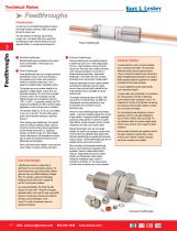
Technical Notes As used here, the word feedthrough applies to devices that transfer all types of services, utilities, and signals through the vacuum wall. The major divisions are electrical, gas and liquid, cryogen (LN2), and optical. While many regard them as feedthroughs, these Technical Notes do not cover viewports (Section 1) or motion devices (Section 8). Electrical feedthroughs are divided into four groups: Power, Instrumentation, Thermocouple, and Ceramic Breaks. Power feedthroughs have one or multiple conductors penetrating the vacuum wall to carry electricity to any powered vacuum device....
Open the catalog to page 2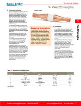
Thermocouple Feedthroughs Thermocouples (T/Cs) are two dissimilar metal wires that meet at a (welded) junction. The junction's temperature and the individual wire's composition determine the voltage difference (often called "EMF" for electromotive force) between the wires' ends. Ideally, each wire's composition is unchanged from junction to the measurement device—nominally a voltmeter. That means the signals should be transferred through the vacuum wall by wires of identical composition too, and that is the function T/C feedthroughs can have one or multiple pairs of wires. The wires are air-side...
Open the catalog to page 3
Technical Notes ➤ Feedthroughs ■ Gas-Liquid Feedthroughs These are mainly for delivering liquids or gases to a vacuum-mounted device, often to maintain the device’s temperature or actuate some gas/liquiddriven rotor. Standard flanges and baseplate ports have one or multiple tubes welded to through-holes, so the tubes extend out on both sides of the flange. The tubes have various diameters and are often terminated with a small flange or gas fitting, such as Swagelok® or Cajon®. For multi-tube feedthroughs, certain combinations of tube diameter/numbers will not fit within certain flange’s ‘‘free’’...
Open the catalog to page 4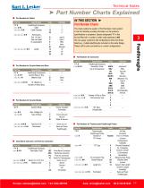
Technical Notes ➤ Part Number Charts Explained ■ Part Numbers for Cables Part No. FTA xxxCBL xxxxxxNN Specification Feedthrough Accessory Cable Cable Diameter type B type C BNC MHV Microdot 12" 24" 36" Terminations End 1 & End 2 (See next table for explanation) IN THIS SECTION ➤ Part Number Charts The charts outline the system of Part Numbers. Each position in the Part Number provides information on the product’s specifications or properties. Spaces designated “N’’ in this list are filled with a number or letter code explained at left. We can supply customers with configurations other than those...
Open the catalog to page 5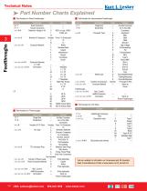
Technical Notes ä Part Number Charts Explained n Part Numbers for Power Feedthroughs n Part Numbers for Instrumentation Feedthroughs Part No. Specification E F T Solid Conductors F T T Tubular Conductors Maximum Voltage in kV x x x N N Number of Conductors x x x x x N x x x x x x N Conductor Material: x x x x x x x N N Conductor Diameter in 1/100” x x x x x x x x x N N Termination CF Code Indicates — — — — 0 500V or Less, 1000V, 1 12,000, etc. 12 Number From 1–9 Conductors V 10 W 12 Nickel 1 2 Stainless Steel 3 Copper 4 Molybdenum 5 Alumel® 6 Constantan 7 Kovar® Part No. Specification IFT Single-End...
Open the catalog to page 6
Power Feedthroughs Power Feedthroughs Style Material Solid Conductor Copper Water-Cooled Conductor Copper Figure 1 (solid conductor) Figure 2 (water-cooled conductor) Figure 2 (2 pins or 2 tubes) Figure 3 (4 pins or 4 tubes) Price Call Call • hese high-voltage, high-current electrical T feedthroughs terminate in baseplates, weldable lips, CF flanges, KF flanges, and male pipe thread • Constructed from vacuum-grade materials, including OFHC copper and nickel conductors, 304 stainless steel mounts, high-purity alumina ceramic insulation, and vacuum-tube grade braze alloys • Units are designed and...
Open the catalog to page 7All Kurt J Lesker catalogs and technical brochures
 TORUS® Linear Magnetrons
2 Pages
 KJL615 digital vacuum
12 Pages
 IMPULSE
2 Pages
 Rotary Vane Vacuum Pumps
2 Pages
 Field Analysis Vacuum Meter
24 Pages
 Shimadzu Turbo Pumps
28 Pages
 Protection Gate Valve
4 Pages
 Electrical Feedthroughs
2 Pages
 UHV Viewports
2 Pages
 2015 UHV Design Catalog
95 Pages
 PowerProbes
11 Pages
 UHV Linear Motion Drives
4 Pages
 EpiCentre - The Deposition Stage
16 Pages
 Pressure Measurement
16 Pages
 Traps & Filters
22 Pages
 Pumps
Pumps98 Pages
 Valves
44 Pages


- Valve
- Manual valve
- Power supply unit
- Control valve
- Stainless valve
- DC power supply
- Pneumatic valve
- Regulating valve
- Flange valve
- Gas valve
- Pneumatically-operated valve
- Gate valve
- Standard valve
- Single-output power supply
- Seat valve
- Compact power supply
- Tabletop power supply
- Flow control valve
- Toroidal seal
- Variable-output power supply