- Company
- Products
- Catalogs
- News & Trends
- Exhibitions
KUKA Palletizing Robots

KUKA Palletizing Robots
- Overview of the Robot System: The system comprises the robot, controller, KCP teach pendant, connecting cables, software, and optional accessories.
- Description of the Robot: The robot features a 5-axis jointed-arm kinematic system made from light alloy and iron castings, driven by AC servomotors with a hydropneumatic counterbalancing system.
- Basic Data: The KR 300 PA and KR 470 PA have a working envelope of 73.5 m³, repeatability of ±0.08 mm, and a reach of 3,150 mm, designed for floor mounting with IP 65 protection.
- Axis Data: Specific range of motion and speed limits for each axis, with KR 300 PA having slightly higher speeds than KR 470 PA.
- General Safety Measures: Covers liability, intended use, and EC declaration of conformity.
- Personnel and Workspace Safety: Guidelines for personnel, workspace, safety zones, and protective equipment.
- Mounting Base and Machine Frame: Instructions for mounting the robot and connecting cables and interfaces.
- Transporting the Robot: Guidelines for safely transporting the robot.
- Requesting Support: Information on contacting KUKA Customer Support for assistance.
Detailed specifications for KR 300 PA and KR 470 PA robots include:
- Rated payloads of 300 kg and 470 kg, with maximum total loads of 350 kg and 520 kg respectively.
- Load center of gravity distances: 100 mm for Lz and 300 mm for Lxy.
- Permissible moment of inertia: 150 kgm2 for KR 300 PA and 235 kgm2 for KR 470 PA.
- Mounting flange specifications: locating diameter of ø 125 H7, screw size M12, and through-hole for energy supply system of ø 60 mm.
Requirements for the robot foundation:
- Concrete grade B25 or C20/25 according to relevant standards.
- Forces and moments: vertical force up to 40,500 N and horizontal force up to 23,500 N.
Provided for STOP 0 and STOP 1 categories for axes 1 to 3:
- KR 300 PA: stopping distances 21.19° to 29.79°, stopping times 0.327s to 0.624s.
- KR 470 PA: stopping distances 18.30° to 41.98°, stopping times 0.338s to 0.808s.
Emphasizes safety and compliance:
- Use in perfect technical condition and as intended.
- Prohibits misuse such as transporting people or operating outside permissible parameters.
- Compliance with EC Machinery Directive required.
- Personnel must be properly instructed and aware of safety protocols.
- Install and connect the robot.
- Conduct risk assessments and implement safety functions.
- Issue declaration of conformity and attach CE mark.
- Create operating instructions for the complete system.
- Operators must be trained and qualified.
- Installation, maintenance, and repair by specially trained personnel.
- Minimize and safeguard workspaces with safety gates.
- Use mechanical end stops and axis range limitations.
- Maintain labeling and warning signs.
- Use robots in perfect technical condition by safety-conscious individuals.
- Prevent burns from motor temperatures.
- Prevent unauthorized use of KCPs and external devices.
- Follow prescribed transport positions.
- Ensure systems are complete and operational before start-up.
- Ensure correct installation and connection of components.
- Used for setup tasks like jogging and programming.
- Test new or modified programs in Manual Reduced Velocity mode (T1).
- Conduct setup work from outside the safeguarded area when possible.
Used for tests requiring higher velocities. Teaching and programming not allowed. Operators must ensure enabling devices are operational and be outside the danger zone.
Permissible only with all safety equipment operational and no persons in the system. If the manipulator stops unexpectedly, do not enter the danger zone until an EMERGENCY STOP is triggered.
Post-maintenance checks required to ensure safety. Work outside the danger zone, or use additional safety measures if inside. Switch off and secure the robot, with EMERGENCY STOP systems active. Replace faulty components with approved parts.
Subject to obligatory monitoring. Work by qualified personnel, following applicable laws and standards.
Avoid skin contact and inhalation of oil spray or vapors. De-energize the system before working on live parts.
Must comply with national laws and standards.
Includes directives like 2006/42/EC Machinery Directive, 2004/108/EC EMC Directive, and various EN ISO standards.
Mounting Base: Requires a level surface on a concrete foundation with specific dimensions and load-bearing capacity.
Machine Frame Mounting: Used for fastening on steel structures, ensuring the substructure can withstand operational forces.
Connecting Cables and Interfaces: Includes motor and control cables with specific lengths and requirements for routing and electromagnetic compatibility.
Robots must be in a transport position before moving. Transport by forklift or lifting tackle, ensuring stability and avoiding damage.
Requesting Support:
Procedure for requesting support from KUKA Roboter GmbH. Essential information includes model and serial numbers, software version, optional software, and a detailed problem description.
KUKA Customer Support:
Available in numerous countries worldwide. Contact details for KUKA subsidiaries and agencies provided. Report faults leading to production downtime within one hour to the local KUKA subsidiary.
Index and Technical Specifications:
Includes an index listing technical specifications, norms, and regulations for KR 300 PA and KR 470 PA models. Covers ambient temperature requirements, axis data, safety measures, maintenance procedures, and transportation guidelines. References European norms and directives.
General Safety and Maintenance:
Highlights general safety measures and maintenance procedures, including preventive maintenance and handling hazardous substances. Discusses labeling, liability, and intended use of robots.
Technical Data and Components:
Provides technical data such as payload diagrams, working envelope, and transport dimensions. Describes principal components of the robot system, including the robot controller, manipulator, and various mechanical and electrical interfaces.
Conclusion:
This document serves as a comprehensive guide for the operation, maintenance, and support of the KR 300 PA and KR 470 PA robotic systems, ensuring users have access to necessary information for efficient and safe use.
Catalog excerpts

Issued: 19.07.2010 Version: Spez KR 300 470 PA V3 en Robots KUKA Roboter GmbH KR 300 PA, KR 470 PA Specification
Open the catalog to page 1
© Copyright 2010 KUKA Roboter GmbH Zugspitzstraße 140 D-86165 Augsburg Germany This documentation or excerpts therefrom may not be reproduced or disclosed to third parties without the express permission of KUKA Roboter GmbH. Other functions not described in this documentation may be operable in the controller. The user has no claims to these functions, however, in the case of a replacement or service work. We have checked the content of this documentation for conformity with the hardware and software described. Nevertheless, discrepancies cannot be precluded, for which reason we are not able...
Open the catalog to page 2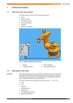
Issued: 19.07.2010 Version: Spez KR 300 470 PA V3 en 5 / 63 1. Product description 1 Product description 1.1 Overview of the robot system The robot system consists of the following components: .. Robot .. Robot controller .. KCP teach pendant .. Connecting cables .. Software .. Options, accessories 1.2 Description of the robot Overview This robot is designed as a 5-axis jointed-arm kinematic system. The structural components of the robots are made of light alloy and iron castings. The axes are driven by AC servomotors. A hydropnuematic counterbalancing system is used to equalize the load moment...
Open the catalog to page 5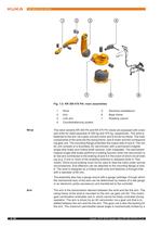
6 / 63 Issued: 19.07.2010 Version: Spez KR 300 470 PA V3 en KR 300 PA, KR 470 PA Wrist The robot variants KR 300 PA and KR 470 PA robots are equipped with a twoaxis wrist for rated payloads of 300 kg and 470 kg, respectively. The wrist is fastened to the arm via a gear unit and motor and is driven by these. The main components of the wrist are the swing frame, axis 6 motor and the corresponding gear unit. The mounting flange embodies the output side of axis 6. The motor unit consists of a brushless AC servomotor with a permanent-magnet single-disk brake and hollow-shaft resolver, both integrated....
Open the catalog to page 6
Issued: 19.07.2010 Version: Spez KR 300 470 PA V3 en 7 / 63 1. Product description stop for each direction, plus and minus. The buffers are attached to the arm. The corresponding stops are situated on the link arm. Link arm The link arm is the assembly located between the arm and the rotating column. It is mounted on one side of the rotating column via the gear unit of axis 2 and is driven by an AC servomotor. During motion about axis 2, the link arm moves about the stationary rotating column. The cable harness of the electrical installations is routed inside the link arm and is mounted in hinged...
Open the catalog to page 7
8 / 63 Issued: 19.07.2010 Version: Spez KR 300 470 PA V3 en KR 300 PA, KR 470 PA
Open the catalog to page 8
Issued: 19.07.2010 Version: Spez KR 300 470 PA V3 en 9 / 63 2. Technical data 2 Technical data 2.1 Basic data Basic data Transport dimensions Ambient temperature Type KR 300 PA KR 470 PA Number of axes 5 Volume of working envelope 73.5 m³ Repeatability (ISO 9283) KR 300 PA ±0.08 mm KR 470 PA ±0.08 mm Working envelope reference point Intersection of axis 6 with the mounting flange face Reach 3,150 mm Weight of robot 1,940 kg Weight of transport frame 212 kg Principal dynamic loads See Loads acting on the foundation Protection classification of the robot IP 65 ready for operation, with connecting...
Open the catalog to page 9
10 / 63 Issued: 19.07.2010 Version: Spez KR 300 470 PA V3 en KR 300 PA, KR 470 PA Connecting cables For connecting cables longer than 25 m an additional ground conductor is provided and must be installed. For detailed specifications of the connecting cables, see (>>> 4.3 "Connecting cables and interfaces" page 45) 2.2 Axis data Axis data The following data are valid for the robot KR 300 PA. The following data are valid for the robot KR 470 PA. * Maximum value, referred to the link arm, depending on the position of axis 2 Start-up +10 °C to +15 °C (283 K to 288 K) At these temperatures the robot...
Open the catalog to page 10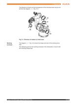
Issued: 19.07.2010 Version: Spez KR 300 470 PA V3 en 11 / 63 2. Technical data The direction of motion and the arrangement of the individual axes may be noted from the diagram (>>> Fig. 2-1). Working envelope The diagram (>>> Fig. 2-2) shows the shape and size of the working envelope. The reference point for the working envelope is the intersection of axis 6 with the mounting flange face. Fig. 2-1: Direction of rotation of robot axes
Open the catalog to page 11
12 / 63 Issued: 19.07.2010 Version: Spez KR 300 470 PA V3 en KR 300 PA, KR 470 PA Fig. 2-2: Working envelope: KR 300 470 PA
Open the catalog to page 12
Issued: 19.07.2010 Version: Spez KR 300 470 PA V3 en 13 / 63 2. Technical data 2.3 Payloads Payloads Load center of gravity P For all payloads, the load center of gravity refers to the distance from the face of the mounting flange on axis 6. Refer to the payload diagram for the nominal distance. Payload diagram Robot KR 300 PA KR 470 PA Wrist Hollow-shaft wrist Hollow-shaft wrist Rated payload 300 kg 470 kg Distance of the load center of gravity Lz 100 mm 100 mm Distance of the load center of gravity Lxy 300 mm 300 mm Permissible moment of inertia 150 kgm2 235 kgm2 Max. total load 350 kg 520...
Open the catalog to page 13
14 / 63 Issued: 19.07.2010 Version: Spez KR 300 470 PA V3 en KR 300 PA, KR 470 PA Mounting flange *The inner locating diameter is ø 125 H7. This deviates from the standard. Fig. 2-4: Payload diagram for KR 470 PA This loading curve corresponds to the maximum load capacity. Both values (payload and principal moment of inertia) must be checked in all cases. Exceeding this capacity will reduce the service life of the robot and overload the motors and the gears; in any such case the KUKA Robot GmbH must be consulted beforehand. The values determined here are necessary for planning the robot application....
Open the catalog to page 14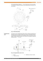
Issued: 19.07.2010 Version: Spez KR 300 470 PA V3 en 15 / 63 2. Technical data The mounting flange is depicted (>>> Fig. 2-5) with axis 6 in the zero position. The symbol Xm indicates the position of the locating element (bushing) in the zero position. Supplementary load The robot can carry supplementary loads on the arm. When mounting the supplementary loads, be careful to observe the maximum permissible total load. The dimensions and positions of the installation options can be seen in the diagram. All other threads and holes on the robot are not suitable for attaching additional loads (>>>...
Open the catalog to page 15All KUKA AG catalogs and technical brochures
 KR 120 R3200 PA-HO
1 Page
 KR 3 D1200 HM
2 Pages
 KMP 600
2 Pages
 KUKA KR IONTEC
2 Pages
 KR CYBERTECH nano
2 Pages
 KUKA KMP 1500
5 Pages
 KUKA Genius-Family
4 Pages
 KUKA Genius V
2 Pages
 KUKA Genius D
2 Pages
 KUKA Genius
2 Pages
 KUKA LBR iisy
13 Pages
 KUKA Robotics_Range
4 Pages
 KUKA smartPAD
2 Pages
 KUKA used robots
4 Pages
 KUKA KR QUANTEC Foundry
2 Pages
 KUKA KR 4 AGILUS
2 Pages
 KUKA robot controller KR C5
2 Pages
 KUKA_KR_C5_micro
2 Pages
 KUKA mobile training cell
2 Pages
 PF0056_KR_5_scara
2 Pages
 Automation for machine tools
11 Pages
 KUKA KMR iiwa
5 Pages
 KUKA Coaster
3 Pages
 KUKA robots for high payload
22 Pages
 KUKA KR C4
14 Pages
 KUKA KR Cybertech
11 Pages
 KUKA ready2_spray
2 Pages
 KUKA ready2_pilot
2 Pages
 KUKA Robotics Robot Range
4 Pages
 KUKA LBR iiwa
18 Pages
 Technology Development
3 Pages
 KUKA energy supply systems
35 Pages
 Productbrochure LOW PAYLOAD
25 Pages
 KUKA MachinetoolsAutomation
11 Pages
 KUKA robots for arc welding
11 Pages
 LBR iiwa Med
4 Pages
 KUKA refurbished robots
4 Pages
 KUKA omniMove
4 Pages
 KR 700 R2510 passenger
4 Pages
 KUKA omniMove tripleLift
5 Pages
 KUKA ready2_use
8 Pages
 KMR QUANTEC
5 Pages
 KUKA Industrie 4.0
34 Pages
 LBR iiwa 7 R800 RAL 9016
17 Pages
 KR 240 R3200 PA arctic
2 Pages
 KR 500 R2830
2 Pages
 KR 6 R700 sixx C-WP
2 Pages
 KUKA Navigation Solution
4 Pages
 KR QUANTEC PA arctic
2 Pages
 KR AGILUS Waterproof
2 Pages
 KUKA Sunrise Cabinet
2 Pages
 Global. Cuetomer. Services
18 Pages


Archived catalogs
 Cleanroom robots
12 Pages
 Compact robots
6 Pages
 KUKA Arc welding
14 Pages
 KUKA KR 1000 titan
6 Pages
 KUKA Customer Services
12 Pages
 Robot Range
2 Pages


- Welding system
- AMOT industrial robot
- AMOT automation software
- Automatic welding machine
- AMOT bending machine
- AMOT process software
- AMOT aerial work platform
- AMOT articulated robot
- AMOT 6-axis robot
- Mobile aerial work platform
- AMOT floor-mounted robot
- AMOT handling robot
- AMOT interface software
- AMOT rotary table
- Electric bending cell
- AMOT programming software
- AMOT electric rotary table
- AMOT compact robot
- Touch screen HMI
- AMOT high-speed robot