

KDF-K
KDF-K
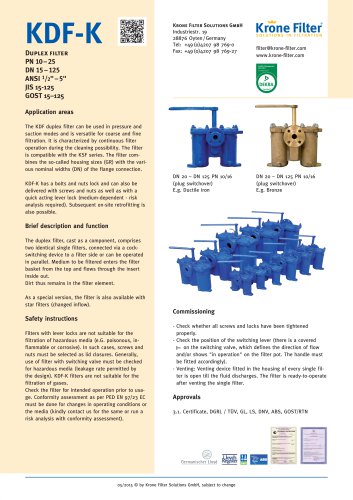
The KDF duplex filter is versatile for both pressure and suction modes, suitable for coarse and fine filtration. It allows continuous operation during cleaning and is compatible with the KSF series. The filter can be retrofitted on-site and is available with different locking mechanisms depending on the medium.
Brief Description and Function
The duplex filter consists of two identical single filters connected via a cock-switching device, allowing for parallel or individual operation. The medium enters from the top, with dirt remaining in the filter element. A special version with star filters is available.
Safety Instructions
Filters with lever locks are unsuitable for hazardous media. For such media, screws and nuts should be used. The filter is not suitable for gases. A conformity assessment as per PED EN 97/23 EC is required for changes in operating conditions.
Commissioning
- Ensure all screws and locks are tightened.
- Check the position of the switching lever.
- Open the venting device until fluid discharges.
Approvals
The filter is certified by various standards including DGRL, TÜV, GL, LS, DNV, ABS, and GOST/RTN.
Cleaning/Operation
Ensure the container is depressurized before maintenance. Switch to the clean filter half when the other is dirty. Open the venting device slowly and drain the remaining fluid.
Technical Data and Dimensions
The document provides detailed dimensions and specifications for various housing sizes and nominal diameters. It includes information on flow rates, filter areas, and weights.
Advantages of KDF-K
- Large ergonomic switching lever.
- Smooth switching due to smoothened surface.
- Combination of connection flanges to housing sizes.
- Dirt remains in the basket strainer.
Technical Data
Includes details on materials, filter elements, and additional features like magnetic filter elements and heaters. The document also outlines the surface treatment options and certifications available.
Conclusion
The KDF duplex filter is a robust and versatile solution for industrial filtration needs, offering various configurations and compliance with international standards.
Catalog excerpts

[email protected] www.krone-filter.com Application areas The KDF duplex filter can be used in pressure and suction modes and is versatile for coarse and fine filtration. It is characterized by continuous filter operation during the cleaning possibility. The filter is compatible with the KSF series. The filter combines the so-called housing sizes (GR) with the various nominal widths (DN) of the flange connection. KDF-K has a bolts and nuts lock and can also be delivered with screws and nuts as well as with a quick acting lever lock (medium-dependent - risk analysis required). Subsequent on-site retrofitting is also possible. DN 20 – DN 125 PN 10/16 (plug switchover) E.g. Ductile iron DN 20 – DN 125 PN 10/16 (plug switchover) E.g. Bronze Brief description and function The duplex filter, cast as a component, comprises two identical single filters, connected via a cockswitching device to a filter side or can be operated in parallel. Medium to be filtered enters the filter basket from the top and flows through the insert inside out. Dirt thus remains in the filter element. As a special version, the filter is also available with star filters (changed inflow). Commissioning Safety instructions Filters with lever locks are not suitable for the filtration of hazardous media (e.G. poisonous, inflammable or corrosive). In such cases, screws and nuts must be selected as lid closures. Generally, use of filter with switching valve must be checked for hazardous media (leakage rate permitted by the design). KDF-K filters are not suitable for the filtration of gases. Check the filter for intended operation prior to usage. Conformity assessment as per PED EN 97/23 EC must be done for changes in operating conditions or the media (kindly contact us for the same or run a risk analysis with conformity assessment). - Check whether all screws and locks have been tightened properly. - Check the position of the switching lever (there is a covered on the switching valve, which defines the direction of flow and/or shows "in operation" on the filter pot. The handle must be fitted accordingly). - Venting: Venting device fitted in the housing of every single filter is open till the fluid discharges. The filter is ready-to-operate after venting the single filter. Approvals 3.1. Certificate, DGRL / TÜV, GL, LS, DNV, ABS, GOST/RTN 05/2015 © by Krone Filter Solutions GmbH, subj
Open the catalog to page 1
Note: Since it is a pressure vessel, it is important to ensure that the container is without pressure prior to beginning of maintenance. DIN EN GJS-500-7 / (GGG-50 / ASTM 80-55-06) alternatively annealed GJS-400-18 / (GGG 40.3) 1. As soon as the filter half is dirty (increasing differential pressure on the indicator or decreasing operating pressure in the system), the clean filter half is put into operation by gradual switching of the plug valve. 2. Proceed with cleaning (removal of filter element) only after opening the venting device slowly and 3. if the filter is build with a pressure equalization...
Open the catalog to page 2
Technical data and dimensions 1 Flange opposite duplex filter with switching valves Option differential pressure indicator Variant lid with screws and nuts Variant lever lock Switching valve marking points towards filter vessel in operation. Fit switching lever accordingly. *Switching direction of the switching lever can be changed by changing the stop. 03 05/2015 © by Krone Filter Solutions GmbH, subject to change
Open the catalog to page 3
Technical data and dimensions 2 Flange opposite duplex filter with switching valves Nominal diameter Flange connection Pressure stage Flow rate Filter overhead space Installation length Lever length Filter area Basket strainer * all dimension subject to modification, as built in approved Krone Filter Solutions drawing. Dimensions only for information – certified dimensions in approved Krone Filter Solutions installation drawing. Foto shows optional - pressure equalization pipe for easy switching 04 05/2015 © by Krone Filter Solutions GmbH, subject to c
Open the catalog to page 4
Technical data Standard version Special version and/or additional features Filter element Basket strainer insert Dual strainer, star strainer, wedged wire Filter unit 25 - 1000 μm: Fabric with support plate, 1 mm onwards: Perforated plate, 1 mm onwards: Perforated plate with round hole Stud screws and nuts Venting device Ball valve Draining device Ball valve Flange as per EN 1092-1 11B Flange position: as against the height ANSI, JIS, as per customer specification GOST Perforated plate/fabric EN GJS-500-7 / (GGG-50 / ASTM 80-55-06) oil version EN GJS-500-7 coated cock with Magna Coat® polymer/flourpolymer...
Open the catalog to page 5
Example KDF-V NW 100 cast iron from product range NW 100-500 Example KDF-W NW 80 SS316 from product range NW 25-500 06 05/2015 © by Krone Filter Solutions GmbH, subject to change DN/NW 80 unit with Dp Indicator Dp-MAG
Open the catalog to page 6All Krone Filter Solutions GmbH catalogs and technical brochures
 automatic Filter
20 Pages
 KMF
KMF12 Pages
 KRF
KRF18 Pages
 KSF
KSF14 Pages
 KWF
KWF6 Pages
 DP-MAG
4 Pages
 KBF-M
KBF-M6 Pages
 KDF-V
KDF-V12 Pages
 KDF-K
KDF-K14 Pages
 KCS Separator
6 Pages
 KAF Bernoulli
14 Pages
 KAF Bernoulli Filter
8 Pages
 KBF
KBF6 Pages
 KBF
KBF3 Pages
 KAF Bernoulli
4 Pages


- Liquid filter
- Pressure gauge
- Industrial use filter
- Pressure separator filter
- Analog pressure gauge
- Stainless steel pre-filter
- Centrifugal classifier
- Liquids separator
- Water pre-filter
- Stainless steel pressure gauge
- Threaded pressure gauge
- Gas pressure gauge
- Waterproof pressure gauge
- Process separator
- Y-strainer filter
- Hydraulic filter
- Compact pre-filter
- Basket filter
- Filter element
- Liquid pressure gauge