- Catalogs
- Krone Filter Solutions GmbH
- KAF Bernoulli
KAF Bernoulli
1 /4Pages

KAF Bernoulli
1 /4Pages
Catalog excerpts

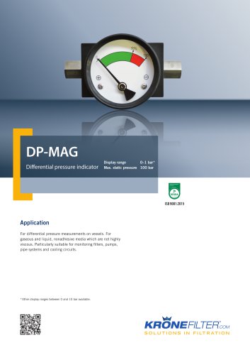
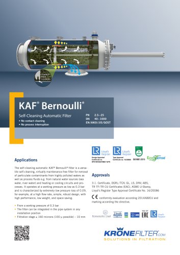
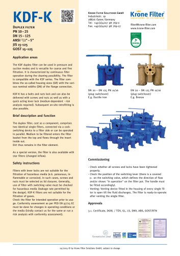
[email protected] www.krone-filter.com Self-Cleaning Automatic Filter Non-Contact Cleaning DN 40 – DN 1000 | PN 2,5 – PN 25 EN / ANSI / JIS / GOST Applications The self-cleaning automatic KAF Bernoulli filter is a versatile self-cleaning, virtually maintenance-free filter for removal of particulate contaminants from highly polluted waters as well as process fluids e.g. from natural water sources (sea water, river water) and heating or cooling circuits and processes. It operates at a working pressure as low as 0.3 bar and is characterized by extremely low pressure loss of 0.09, for example, at a high flow rate, simple, robust design, with high performance, low weight, and space saving. Electronic standard multifunctional unit of the KAF filter. Alternatively Siemens or Allen Bradley/Rockwell for controlling up to 10 filters. Flush outlet • from a working pressure of 0.3 bar • the filter can be integrated in the pipe system in any installation position • filtration stage ≥ 160 microns (100 μ possible) - 10 mm Inlet Brief description of operation Functional description of the cleaning process A specially shaped flushing disk gives rise to an increase in speed between the disk and strainer in the flushing process. The resulting local pressure drop causes internal evacuation of the contaminant particles from the strainer insert. Solid components are flushed out via the simultaneously opened flush valve. The filter is equipped with a differential pressure monitoring system that automatically triggers the flushing process before any blockages in the filter strainer cause significant flow reductions. The flushing process can also take place after a predetermined time. • Filtrate flow is not interrupted in this process; the flushing volumes are low. • The pressure drop in the system is minimal. The contaminated medium flows into the filter through the flange marked inlet. The contaminated medium flows through the filter insert from the inside to the outside and exits out of the flange marked outlet as cleaned medium. The flushing phase of the filter is either activated when the set differential pressure is attained, or the flushing phase is activated after a set time interval. The flushing valve opens and larger contaminant particles are flushed out with the continuously flowing medium stream due to a pressure gradient. Subsequently the piston usually performs two strokes in the filter strainers, thereby increasing the speed between the piston and strainer wall. The contaminants are sucked off due to the resultant local pressure drop. The flushing time can be set by the controller according to the operating conditions, and flushing frequency depends on the level of contamination in the medium. Installation Operating instructions: The comprehensive instructions accompanying the filter must be followed! The filter is installed in pipes using flanges. Ensure that the standard version of the filter is installed vertically or horizontally in a mechanically stress-free manner without additional loads. The medium must flow in the direction specified on the housing. Incorrect installation can cause filter malfunctions. If the contaminant drain pipe is laid with an ascending gradient ensure that the inlet pressure of the filter is at least a 0.3 bar higher than the counter pressure in the contaminant drain pipe (pay attention to the loss through friction in pipes). Before using with a medium other than the medium specified in the design, or for different operating data, the resistance of the materials of the parts and seals touched by the pressure-bearing membrane to the medium to be filtered must be checked by the customer; it may be necessary to consult with the manufacturer and to execute a conformity evaluation in accordance with PED EN 97 / 23 EC (if there is a CE-mark requirement). 01 04/2014 © by Krone Filter Solutions GmbH, su
Open the catalog to page 1
Technical data Standard Special versions Filter insert/filtration degree Filter cover Cover with hex bolts + nuts Venting device Drain unit As specified by the customer (e.g. ANSI, JIS) Cast Iron (rubberlined) Stainless steel Cast Iron GRP / FRP (polyester-based fiber-reinforced plastic) 1.4571, steel GGG50 / EN-GJS-500-7 / ASTM-80-55-06 Perforated plate/slotted hole strainer Titan, Hastelloy, Monel, Super Duplex, Uranus Flushing disk Differential pressure switch Ms chem. nickel-plated (Membrane) Hastelloy, Monell (Membrane) Differential pressure switch Electrical with 1st contact for start of...
Open the catalog to page 2
Flush outlet Filter dimensioning chart pressure loss Dimensioning example (0.22 mm filtration degree) / selection chart at 500 m3/h, the use of a DN 200 or DN 250 is recommended at 200 μm. Flanges in accordance with EN 1092-1 PN10-16 or ANSI 16.5 150 lbs D2 Flow rate *** Example flushing volume/backflush (adjustable) *Dependent on pressure phase, **Rubberlined on request, ***Dependent on filtration degree
Open the catalog to page 3
Cast Iron (EN-GJS-500-7 / GGG-50 / ASTM 80-55-06) Flow rate *** Example flushing volume/backflush (adjustable) *Dependent on pressure phase, ***Dependent on filtration degree 24" / DN 600 KAF Filter seawater cooling 14" / DN 350 Filter seawater cooling for use in Ex Zone 1 200 JIS / DN 200 ship seawater cooling for use in Ex Zone 1 300 JIS / DN 300 ship seawater cooling for use in Ex Zone 1 04 04/2014 © by Krone Filter Solutions GmbH, subject to change
Open the catalog to page 4All Krone Filter Solutions GmbH catalogs and technical brochures
 automatic Filter
20 Pages
 KMF
KMF12 Pages
 KRF
KRF18 Pages
 KSF
KSF14 Pages
 KWF
KWF6 Pages
 DP-MAG
4 Pages
 KBF-M
KBF-M6 Pages
 KDF-V
KDF-V12 Pages
 KDF-K
KDF-K14 Pages
 KCS Separator
6 Pages
 KAF Bernoulli
14 Pages
 KAF Bernoulli Filter
8 Pages
 KBF
KBF6 Pages
 KDF-K
KDF-K6 Pages
 KBF
KBF3 Pages


- Liquid filter
- Pressure gauge
- Pressure separator filter
- Industrial use filter
- Analog pressure gauge
- Stainless steel pre-filter
- Centrifugal classifier
- Water pre-filter
- Liquids separator
- Stainless steel pressure gauge
- Threaded pressure gauge
- Gas pressure gauge
- Waterproof pressure gauge
- Y-strainer filter
- Process separator
- Compact pre-filter
- Basket filter
- Hydraulic filter
- Filter element
- Liquid pressure gauge