- Catalogs
- KRACHT GmbH
- High pressure gear pumps KP 2 / KP 3
High pressure gear pumps KP 2 / KP 3
1 /18Pages

High pressure gear pumps KP 2 / KP 3
1 /18Pages
Catalog excerpts

Gear Pumps
Open the catalog to page 1
High-Pressure Gear Pumps KP 2 / KP 3
Open the catalog to page 2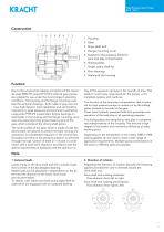
High-Pressure Gear Pumps KP 2 / KP 3 High Pressure Gear Pumps KP 2 / KP 3 1 Housing 2 Gear 3 Drive shaft end 4 Flange mounting cover 5 Gasket for the pressure fields for axial and play compensation 6 Sliding plates 7 Single rotary shaft lip 8 Plain bearings 9 Sealing of the housing Function Due to the construction (design principle) and the materials used KRACHT series KP 2 / KP 3 external gear pumps are suitable for use under the most stringent operating conditions. The housing and the flange mounting cover (see the sectional drawing) – both made of gray cast iron – have high dynamic load capabilities...
Open the catalog to page 3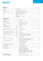
High Pressure Gear Pumps KP 2 / KP 3 High-Pressure Gear Pumps KP 2 / KP 3 Materials Housing grey cast iron composite plain bearing bushes case hardening steel acc. to DIN 17210 surface hardened and ground NBR rotary shaft lip type seal ϑ 90 °C FKM rotary shaft lip type seal ϑ 150 °C Characteristics Mounting flange type Pipe connection Mounting position Ambient temperature Operating pressure Inlet port Operating pressure Short time Operating pressure Outlet port Fluid temperature range 90 °C for NBR rotary shaft lip type seal 150 °C for FKM rotary shaft lip type seal νmin νmax according to ISO...
Open the catalog to page 4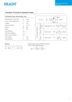
High-Pressure Gear Pumps KP 2 / KP 3 High Pressure Gear Pumps KP 2 / KP 3 Calculation Formulas for Hydraulic Pumps Characteristic data, formula signs, units Total efficiency Volumetric efficiency Hydr./mech. efficiency Flow velocity Pipe diameter Pump / motor displacement Torque Volumetric flow Discharge flow / input flow Drive torque Input power Approximate values for KRACHT products in the nominal operating point ηtot ηvol KP KRACHT GmbH · Gewerbestr. 20 · 58791 Werdohl, Germany · Phone +49 23 92.935-0 · Fax +49 23 92.935 209 · Email info@krac
Open the catalog to page 5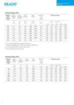
High-Pressure Gear Pumps KP 2 / KP 3 High Pressure Gear Pumps KP 2 / KP 3 Technical Data KP2 Displacement Nominal size Peak pressure Minimum speed Geom. displacement S1 or S3 mode (50 % operating factor 30 1/min) Pressure data applies for ν м 30 mm2/s and n м 1000 1/min For housing with SAE connection Ø 32 / Ø 40 For housing with connection Ø 26 Technical Data KP3 Displacement Nominal size Minimum speed Peak pressure Geom. displacement
Open the catalog to page 6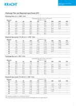
High-Pressure Gear Pumps KP 2 / KP 3 High Pressure Gear Pumps KP 2 / KP 3 Discharge Flow and Required Input Power KP2 Discharge flow at n = 1450 1/min Discharge flow Q in l/min at 34 mm2/s Pressure p in bar 100 140 180 200 Nominal size Required input power P in kW at n = 1450 1/min Nominal size Discharge flow at n = 950 1/min Discharge flow Q in l/min at 34 mm2/s Pressure p in bar 100 140 180 200 Nominal size Required input power P in kW at n = 950 1/min Nominal size The ratings are based on a viscosity of 34 mm2 The output of the drive motor must be chosen 20 % higher than the table value P...
Open the catalog to page 7
High-Pressure Gear Pumps KP 2 / KP 3 High Pressure Gear Pumps KP 2 / KP 3 Discharge Flow and Required Input Power KP3 Discharge flow at n = 1450 1/min Nominal size Discharge flow Q in l/min at 34 mm2/s Pressure p in bar 100 140 180 200 Required input power P in kW at n = 1450 1/min Pressure p in bar 140 180 Nominal size Discharge flow at n = 950 1/min Discharge flow Q in l/min at 34 mm2/s Pressure p in bar 100 140 180 200 Nominal size Required input power P in kW at n = 950 1/min Pressure p in bar 140 180 Nominal size The ratings are based on a viscosity of 34 mm2/s The output of the drive motor...
Open the catalog to page 8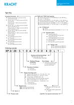
High-Pressure Gear Pumps KP 2 / KP 3 High Pressure Gear Pumps KP 2 / KP 3 Type Key Shaft end / Shaft load capacity B External spline W 35 x 2; DIN 5480 from Vg 82; 800 Nmmax K Cone 1 : 5; 500 Nmmax U External spline SAE-B; Z = 13; DP 16/32; α = 30°; 180 Nmmax Y Cylindrical shaft Ø 24; 230 Nmmax KP 2; Ø 32; 550 Nmmax KP 3 W External spline B 28 x 25; DIN 5482; Z = 15; m = 1.75; 450 Nmmax Q External spline SAE C; Z = 14; DP 12/24; α = 30°; 500 Nmmax Housing connection A Suction and pressure connection Ø 26 with LK 55 to Vg 50 F Suction side 1 1⁄ 4"-SAE connection (Ø 32) to Vg size 32 Pressure side...
Open the catalog to page 9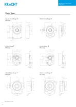
High-Pressure Gear Pumps KP 2 / KP 3 High Pressure Gear Pumps KP 2 / KP 3 Flange Types Square 4-hole flange G KP 2 only KRACHT GmbH · Gewerbestr. 20 · 58791 Werdohl, Germany · Phone +49 23 92.935-0 · Fax +49 23 92.935 209 · Email [email protected] · Web www.kracht.eu
Open the catalog to page 10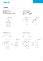
High-Pressure Gear Pumps KP 2 / KP 3 High Pressure Gear Pumps KP 2 / KP 3 Housing connection A Displacement nominal size KP 2: 20 – 50 Inlet and outlet ports same dimensions Displacement nominal size KP 2: 20, 25, 28, 32 Inlet port Outlet port SAE 1 SAE 11⁄4 Displacement nominal size KP2: 40, 50, 62 KP3: 63-71 Inlet port Outlet port SAE 11⁄4 SAE 11⁄2 Outlet port SAE 11⁄4 M 12 - 25 deep KRACHT GmbH · Gewerbestr. 20 · 58791 Werdohl, Germany · Phone +49 23 92.935-0 · Fax +49 23 92.935 209 · Email [email protected] · Web www.kracht.eu
Open the catalog to page 11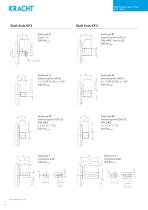
High-Pressure Gear Pumps KP 2 / KP 3 High Pressure Gear Pumps KP 2 / KP 3 Shaft Ends KP 3 Shaft end K Cone 1 : 5 500 Nmmax Shaft end B External spline W 35 x 2 DIN 5480 from Vg 82 800 Nmmax Shaft end U External spline SAE-B z = 13 DP 16 / 32, α = 30° 180 Nmmax Shaft end Q External spline SAE-C z = 14 DP 12 / 24, α = 30° 500 Nmmax Shaft end W External spline B 28 x 25 DIN 5482 z = 15, m = 1.75 450 Nmmax Shaft end W External spline B 28 x 25 DIN 5482 z = 15, m = 1.75 450 Nmmax Shaft end Y Cylindrical shaft 230 Nmmax Shaft end Y Cylindrical shaft 550 Nmmax KRACHT GmbH · Gewerbestr. 20 · 58791 Werdohl,...
Open the catalog to page 12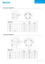
High-Pressure Gear Pumps KP 2 / KP 3 Druckbegrenzungsventile KP 2 / KP 3 High Pressure Gear Pumps SPV, SPVF direktgesteuert Aufbau Dimensions, Weight KP 2 P Displacement Nominal size Das Druckbegrenzungsventil SPV/ SPVF ist ein direktgesteuertes Schieberventil für Einbau in Rohrleitungen und dient zur Absicherung von Niederdruck-HydraulikKreisläufen. Der Leitungs-Anschluss kann mittels SAEFlansch (3000 psi) oder Whitworth-Rohrgewinde (G) vorgenommen werden. Der Ventilschieber 2 wird durch die Druckfeder 3 gegen die Ringfläche a gedrückt und sperrt somit über den Durchmesser d den Druckanschluss...
Open the catalog to page 13All KRACHT GmbH catalogs and technical brochures
 Hydraulic cylinder CNL
18 Pages
 High pressure gear motors KM 5
10 Pages
 High pressure gear motors KM 3
12 Pages
 High pressure gear motors KM 2
16 Pages
 High pressure gear motors KM 1
30 Pages
 Pressure relief valves DBD
12 Pages
 Pressure valves DV
14 Pages
 Turbine flow meters TM
9 Pages
 Screw type flow meters SVC
28 Pages
 Gear type flow meters VCA / VCG
16 Pages
 Gear type flow meters VC
36 Pages
 High pressure gear pump KP 5
12 Pages
 High pressure gear pumps KP 1
22 Pages
 High pressure gear pumps KP 0
12 Pages
 Gear pumps DT DuroTec
12 Pages
 Gear pumps KP 1 DuroTec
16 Pages
 Gear metering pumps ADP
12 Pages
 Gear pumps BT/BTH
16 Pages
 Gear pumps KF 730 ... 1500
16 Pages
 Gear pumps KF 2.5 ... 630
40 Pages


- Bourn And Koch industrial pump
- Bourn And Koch electric pump
- Bourn And Koch stationary pump
- Bourn And Koch self-priming pump
- Bourn And Koch chemical pump
- Bourn And Koch flow meter
- Bourn And Koch stainless steel pump
- Cylinder
- Bourn And Koch lubricant pump
- Bourn And Koch volume flow meter
- Bourn And Koch liquid flow meter
- Bourn And Koch oil pump
- Bourn And Koch transfer pump
- Bourn And Koch pump for the chemical industry
- Double-acting cylinder
- Bourn And Koch metering pump
- Hydraulic cylinder
- Bourn And Koch stainless steel flow meter
- Bourn And Koch cast iron pump