
- Catalogs
- KRACHT GmbH
- High pressure gear pumps KP 1

High pressure gear pumps KP 1

High pressure gear pumps KP 1
The document outlines the technical specifications and operational guidelines for the KRACHT KP 1 series high-pressure gear pumps, known for their high manufacturing quality and efficiency.
Construction and Materials
The KP 1 series pumps have an aluminium housing, with an option for cast iron, and include components such as gearing and gland bearings. The gears are crafted from case hardening steel, which is surface hardened and ground for precision. The pumps utilize NBR and FKM rotary shaft lip-type seals, suitable for various temperature ranges.
Functionality
These pumps are designed to reduce volumetric flow deviation and pressure pulsation using a high number of specially shaped teeth. They feature double-gland bearings with multicomponent plane bearing bushes and pressure field sealing for axial clearance compensation.
Operational Guidelines
External loads on the drive shaft end can affect the pump's function. While radial loads are manageable, axial loads are not allowed. The flow direction is influenced by the rotation direction: clockwise rotation moves flow from left to right, and anticlockwise from right to left.
Technical Specifications
- Mounting: Flange and foot-type
- Operating Pressure: Inlet port: -0.4 to 2 bar, Outlet port: see technical data
- Temperature Range: Ambient: -20°C to 60°C, Fluid: up to 100°C
- Viscosity Range: 10 to 600 mm²/s
- Hydraulic Fluids: Mineral oil, engine oil, and bio-oils (up to 70°C)
Performance Data
The document includes charts for discharge flow and required input power at various pressures and speeds, along with formulas for calculating discharge flow, torque, and input power, highlighting operational efficiency.
Ordering Information
Details on the type key for ordering are provided, including options for seals, nominal displacement, flange types, direction of rotation, and shaft end configurations, with examples of ordering codes for specific configurations.
Diagrams and Dimensions
Diagrams illustrate the dimensions and configurations of various flange and shaft end types, offering essential information for installation and compatibility.
Catalog excerpts

Gear Pumps
Open the catalog to page 1
High-Pressure Gear Pumps KP 1
Open the catalog to page 2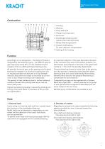
High-Pressure Gear Pumps KP 1 High Pressure Gear Pumps KP 1 Housing Gearing Drive shaft end Flange mounting cover End cover Double-gland bearing with special plane bearing bushes 7 Rotary shaft lip-type seals 8 Pressure field sealing for axial clearance compensation 9 Sealing of the housing Function Accordingly to its configuration – the Design Principle is illustrated by the Sectional Figure – the KRACHT external gear type pump series KP 1 is to be classified into the category of the so-called gland type bearing pumps. An important reduction of the type dependent deviation of the volumetric...
Open the catalog to page 3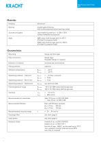
High-Pressure Gear Pumps KP 1 High Pressure Gear Pumps KP 1 Materials Housing double-gland bearing with multicomponent plane bearing bushes case hardening steel acc. to DIN 17210 surface hardened and ground NBR rotary shaft lip type seal ϑ ≤ 90 °C (PU-Seal for pressure field) FKM rotary shaft lip type seal ϑ ≤ 100 °C (PU-Seal for pressure field) Characteristics Mounting Pipe connection flange type, threaded flange on request Fitting position Ambient temperature Operating pressure Inlet port Operating pressure Short time Operating pressure Outlet port Fluid temperature range 90 °C for NBR rotary...
Open the catalog to page 4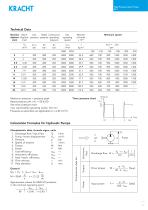
High-Pressure Gear Pumps KP 1 High Pressure Gear Pumps KP 1 Technical Data Nominal Geom. max. Rated Continuous displace- displace- pressure pressure operating ment ment pressure Vg cm3/r Minimum speed Maximum pressure = pressure peak Rated pressure pN < 6 s = 50 % ED See time / pressure chart max. permissible operating cycles: 30 / min Pressures as specified are applicable to ν ≥ 30 mm2/s Time / pressure chart Calculation Formulas for Hydraulic Pumps Volumetric flow Approximate values for KRACHT products in the nominal operating point ηtot ηvol Drive torque Characteristic data, formula signs,...
Open the catalog to page 5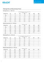
High-Pressure Gear Pumps KP 1 High Pressure Gear Pumps KP 1 Discharge Flow and Required Input Power Discharge flow at n = 1450 1/min Nominal size Required input power at n = 1450 rpm Nominal size Discharge flow at n = 950 1/min Nominal size Required input power at n = 950 rpm Nominal size KRACHT GmbH · Gewerbestr. 20 · 58791 Werdohl, Germany · fon +49 (0) 23 92
Open the catalog to page 6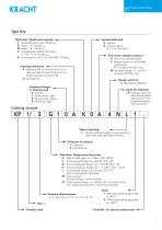
High-Pressure Gear Pumps KP 1 High Pressure Gear Pumps KP 1 Type Key Second shaft end 0 without X Involute spline Shaft end / Shaft load capacity F Parallel flat shaft end / 40 Nm max K Taper 1 : 5 / 160 Nm max M Taper 1 : 8 / 160 Nm max S Involute spline SAE-A, DP 16/32, End covers (adaptor pieces) A End cover (standard type) F Adaptor piece for multi-stage pump types: KP 1 coupled with KP 1 only W the same as type „F“ but KP 1 coupled with KP 0 only Housing side ports A Inlet port dia. 15 with PC 40 to Vg 5.5 Inlet port dia. 20 with PC 40 to Vg 6.3 Outlet port dia. 15 with PC 35 Design serial...
Open the catalog to page 7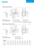
High-Pressure Gear Pumps KP 1 High Pressure Gear Pumps KP 1 G-Flange, Tapered Shaft End 90 Outlet port Inlet port Ordering example: The direction of rotation as represented is clockwise Shaft end: Taper 1: 5 Hex. lock nut M 12 x 1.5 DIN EN 28675 Curved spring washer B 12 DIN 137 Woodruff key 3 x 6.5 DIN 6888 In case of anticlockwise rotation the inlet and outlet ports are opposite G-Flange, Involute Spline Shaft End 23.5 F Outlet port Inlet port Ordering example: Shaft end: Involute spline B 17 x 14 DIN 5482 but tooth thickness Sw = 3.206 Addendum modification = + 0.6 Nominal displacement
Open the catalog to page 8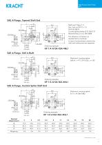
High-Pressure Gear Pumps KP 1 High Pressure Gear Pumps KP 1 SAE A-Flange, Tapered Shaft End 38 The direction of rotation as represented is clockwise In case of anticlockwise rotation the inlet and outlet ports are opposite Outlet port Shaft end: Taper 1: 5 Hex. lock nut M 12 x 1.5 DIN EN 28675 Curved spring washer B 12 DIN 137 Woodruff key 3 x 6,5 DIN 6888 Ordering example: Inlet port Shaft end: Involute spline SAE-A z = 9 T, DP 16/32; α = 30° Outlet port Ordering example: Inlet port SAE A-Flange, Involute Spline Shaft End 23.5 Outlet port Shaft end: Involute spline B 17 x 14 DIN 5482 Ordering...
Open the catalog to page 9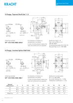
High-Pressure Gear Pumps KP 1 High Pressure Gear Pumps KP 1 K-Flange, Tapered Shaft End 1 : 8 E Outlet port The direction of rotation as represented is clockwise Ordering example: Shaft end: Taper 1: 8 Hex. lock nut M 12 x 1.5 DIN EN 28675 Curved spring washer B 12 DIN 137 Woodruff key 3 x 6.5 DIN 6888 In case of anticlockwise rotation the inlet and outlet ports are opposite K-Flange, Involute Spline Shaft End E Outlet port Ordering example: The direction of rotation as represented is clockwise Shaft end: Involute spline B 17 x 14 DIN 5482 but tooth thickness Sw = 3.206 Addendum modification...
Open the catalog to page 10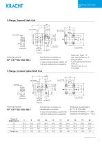
High-Pressure Gear Pumps KP 1 High Pressure Gear Pumps KP 1 F-Flange, Tapered Shaft End E Outlet port Inlet port Shaft end: Taper 1: 5 Hex. lock nut M 12 x 1.5 DIN EN 28675 Curved spring washer B 12 DIN 137 Woodruff key 3 x 6.5 DIN 6888 The direction of rotation as represented is clockwise Ordering example: In case of anticlockwise rotation the inlet and outlet ports are opposite F-Flange, Involute Spline Shaft End 26 Outlet port Inlet port Ordering example: The direction of rotation as represented is clockwise Shaft end: Involute spline B 17 x 14 DIN 5482 but tooth thickness Sw = 3.206 Addendum...
Open the catalog to page 11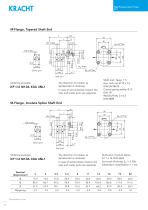
High-Pressure Gear Pumps KP 1 High Pressure Gear Pumps KP 1 M-Flange, Tapered Shaft End E Outlet port Inlet port Ordering example: Shaft end: Taper 1: 5 Hex. lock nut M 12 x 1.5 DIN EN 28675 Curved spring washer B 12 DIN 137 Woodruff key 3 x 6.5 DIN 6888 The direction of rotation as represented is clockwise In case of anticlockwise rotation the inlet and outlet ports are opposite M-Flange, Involute Spline Shaft End E Outlet port Inlet port The direction of rotation as represented is clockwise Ordering example: Shaft end: Involute spline B 17 x 14 DIN 5482 but tooth thickness Sw = 3.206 Addendum...
Open the catalog to page 12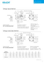
High-Pressure Gear Pumps KP 1 High Pressure Gear Pumps KP 1 Q-Flange, Tapered Shaft End E O-Ring extent of Kracht delivery Outlet port Inlet port Ordering example: Shaft end: Taper 1: 5 Hex. lock nut M 12 x 1.5 DIN EN 28675 Curved spring washer B 12 DIN 137 Woodruff key 3 x 6.5 DIN 6888 The direction of rotation as represented is clockwise In case of anticlockwise rotation the inlet and outlet ports are opposite Q-Flange, Involute Spline Shaft End E O-Ring extent of Kracht delivery Outlet port Inlet port Ordering example: The direction of rotation as represented is clockwise Shaft end: Involute...
Open the catalog to page 13All KRACHT GmbH catalogs and technical brochures
 Hydraulic cylinder CNL
18 Pages
 High pressure gear motors KM 5
10 Pages
 High pressure gear motors KM 3
12 Pages
 High pressure gear motors KM 2
16 Pages
 High pressure gear motors KM 1
30 Pages
 Pressure relief valves DBD
12 Pages
 Pressure valves DV
14 Pages
 Turbine flow meters TM
9 Pages
 Screw type flow meters SVC
28 Pages
 Gear type flow meters VCA / VCG
16 Pages
 Gear type flow meters VC
36 Pages
 High pressure gear pump KP 5
12 Pages
 High pressure gear pumps KP 0
12 Pages
 Gear pumps DT DuroTec
12 Pages
 Gear pumps KP 1 DuroTec
16 Pages
 Gear metering pumps ADP
12 Pages
 Gear pumps BT/BTH
16 Pages
 Gear pumps KF 730 ... 1500
16 Pages
 Gear pumps KF 2.5 ... 630
40 Pages


- KRACHT industrial pump
- Pump with electric motor
- Stationary pump
- Self-priming pump
- KRACHT chemical pump
- Flowmeter
- Stainless steel pump
- Cylinder
- Volume flow monitor
- KRACHT lubricant pump
- Liquid flow monitor
- KRACHT oil pump
- KRACHT transfer pump
- Pump for the chemical industry
- Double-acting cylinder
- Metering pump
- Hydraulic cylinder
- Stainless steel flow monitor
- Cast iron pump