
- Catalogs
- Koyo Seiko
- General New Catalogue

General New Catalogue
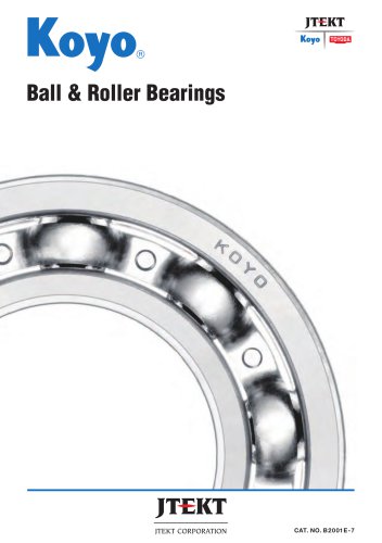
General New Catalogue
Rolling bearings consist of bearing rings, rolling elements, and a cage. They are classified by the number of rows of rolling elements: single-row, double-row, or multi-row. The document details various types of rolling elements, including balls and rollers, and different cage types, emphasizing their suitability for high-speed rotation due to lower friction resistance.
The selection process involves choosing the appropriate bearing type, arrangement, and dimensions based on service life calculations, load calculations, and dynamic/static load ratings. The document provides guidelines for selecting the correct bearing for specific applications.
This section outlines the boundary dimensions and bearing numbers, including dimensions of snap ring grooves and locating snap rings.
Details on tolerances and tolerance classes for bearings are provided, along with methods for measuring these tolerances.
Information on correcting limiting speed, considerations for high-speed applications, and frictional coefficients is included.
The document discusses the purpose of fits, tolerance and fit for shaft and housing, fit selection, and recommended fits.
Guidelines for selecting internal clearance, operating clearance, and preload methods are provided, along with their purposes and effects on rigidity.
The purpose and methods of lubrication are discussed, including types of lubricants suitable for different applications.
Information on materials used for bearing rings, rolling elements, and cages is provided, highlighting their importance in bearing performance.
Design considerations for shafts and housings, including accuracy, roughness, and sealing devices, are detailed.
Instructions for handling, storage, mounting, and dismounting of bearings are provided, along with methods for analyzing bearing failures.
The document introduces various bearing products, including deep groove ball bearings, angular contact ball bearings, and specialized bearings for specific applications like railway rolling stock and machine tool spindles.
Supplementary tables provide boundary dimensions, tolerances, and conversion factors, while the index aids in navigating the document.
This section describes various types of thrust bearings, including cylindrical roller, needle roller, tapered roller, and spherical thrust roller bearings. Each type is characterized by its structure, load capacity, and application suitability. For instance, cylindrical roller thrust bearings are suitable for high axial load resistance and are commonly used in oil excavators and steel equipment. Needle roller thrust bearings are noted for their compact size, making them ideal for applications with limited space, such as automotive transmissions. Tapered roller thrust bearings can handle axial loads in one or both directions, depending on the configuration, and are used in crane hooks and rolling mills. Spherical thrust roller bearings are self-aligning and can accommodate both axial and a small amount of radial load, making them suitable for hydroelectric generators and vertical motors.
The selection process for bearings involves considering various operating conditions and performance requirements. Key factors include installation space, load magnitude and direction, rotational speed, running accuracy, rigidity, and misalignment. The document provides a comprehensive guide to selecting the appropriate bearing type based on these factors, emphasizing the importance of understanding the specific application requirements and the characteristics of different bearing types.
This section outlines the criteria for selecting the appropriate bearing type, including installation space, load characteristics, rotational speed, running accuracy, rigidity, and misalignment. It provides a comparison of different bearing types, such as deep groove ball bearings, angular contact ball bearings, and cylindrical roller bearings, highlighting their suitability for various applications based on these criteria.
The arrangement of bearings on a shaft is crucial for optimal performance. Typically, one bearing is mounted on the fixed side to determine the shaft's axial position, while another is mounted on the free side to accommodate thermal expansion and contraction. The document recommends specific bearing types for fixed and free side applications, such as deep groove ball bearings and cylindrical roller bearings, based on their ability to handle radial and axial loads.
Bearings are used in various configurations to accommodate different loads and operational conditions. Angular contact ball bearings or tapered roller bearings are often used in pairs to handle axial loads. After mounting, axial clearance is adjusted using nuts or shims. Bearings that can handle both radial and axial loads are recommended for the fixed side, while those that handle only radial loads are used on the free side to compensate for shaft movement.
2. Example Bearing Arrangements
Several examples illustrate different bearing arrangements for specific applications:
- Ex. 1: Suitable for high-speed operations, not recommended for applications with center displacement.
- Ex. 2: Suitable for heavy load or impact load, with separability for interference applications.
- Ex. 3: Recommended for heavier impact loads, requiring high rigidity and accurate dimensions.
- Ex. 4: Suitable for high-speed operations with lighter axial loads.
- Ex. 5: Recommended for small axial loads and interference applications.
- Ex. 6: Suitable for high-speed and heavy radial loads.
- Ex. 7: Widely employed for partial axial and radial loads.
3. Bearing Service Life
Bearing service life is affected by material fatigue, leading to flaking. The basic rating life is defined as the number of revolutions until 90% of bearings remain without flaking. Factors such as wear, seizure, and cracking can also affect bearing life. Proper mounting and lubrication can minimize these failures.
4. Calculation of Service Life
The basic dynamic load rating (C) is used to calculate the basic rating life (L10), which is the service life with 90% reliability. Equations are provided to express the basic rating life in terms of time or distance, depending on the application.
5. High Temperature and Dimension Stabilizing Treatment
High temperatures can reduce material hardness, affecting the basic dynamic load rating. Temperature coefficients are used to correct these ratings. Dimension stabilizing treatments are necessary for extended operation at high temperatures, with specific codes and temperature ranges provided.
6. Modified Rating Life
To align calculated life with actual life, a modified rating life considers factors such as bearing materials and usage conditions. This has been standardized in ISO 281 and JIS B 1518.
- The modified rating life (Lnm) is calculated using the equation Lnm = a1 aISO L10, where L10 is the basic rating life with 90% reliability.
- Factors affecting Lnm include reliability, fatigue load limit, lubrication contamination, and special operating conditions.
- a1 - Reliability Factor: Defined as the percentage of bearings expected to meet or exceed a specified life. Table 5-3 provides values for different reliability percentages.
- aISO - System Approach: Considers the interdependent influences on bearing life, calculated using the equation aISO = f(ec Cu/P, κ).
- Fatigue Load Limit (Cu): The load under which the fatigue stress limit is reached, influenced by bearing type, size, and material.
- Contamination Factor (ec): Accounts for the impact of lubricant contamination on bearing life, with values provided in Table 5-4.
- Viscosity Ratio (κ): The ratio of actual to reference kinematic viscosity, affecting the oil film status on the roller contact surface.
- Table 5-5 outlines recommended service life for various applications, ranging from household appliances to industrial machinery.
- Loads affecting bearings include forces from weight, transmission devices, and operational conditions.
- Load coefficients (fw) are used to adjust theoretical values for actual conditions, as shown in Table 5-6.
- Equations for calculating loads from belt, chain, and gear transmissions are provided, with coefficients for each type of transmission.
- Spur Gears: Axial load (Kr) is calculated using the formula Kr = Kt tan α.
- Helical Gears: Kr = Kt, with additional factors involving angles α and β.
- Double-Helical Gears: Similar to helical gears but with specific angle considerations.
- Bevel Gears: Different formulas for drive and driven sides, involving angles δ and α.
- Radial and axial forces are calculated for bearings A and B, considering external loads and moments.
- Equations provided for calculating perpendicular and horizontal radial component forces.
- Dynamic equivalent load (P) is calculated for bearings under combined radial and axial loads.
- Equations provided for radial and thrust bearings, with factors X and Y from bearing specifications.
- Basic static load rating is defined by contact stress limits for different bearing types.
- Static equivalent load is calculated for radial and thrust bearings using specific equations.
- Maximum allowable axial load is calculated using empirical coefficients and mean diameter values.
- Examples provided for calculating bearing service life with different reliability percentages.
The document provides detailed calculations for bearing service life and load ratings. It includes formulas for dynamic equivalent radial load (Pr) and service life (L10h) using specific equations. The basic load ratings (Cr, C0r) and factors (f0, X, Y) are derived from bearing specification tables.
Example Calculations:
Several examples illustrate the calculation of service life and load ratings for different bearing types under various conditions. These include tapered roller bearings and deep groove ball bearings, with specific loads and rotational speeds.
Lubrication and Reliability:
The document discusses the selection of lubricating oil based on operating temperature and viscosity. It calculates the aISO factor for reliability and service life with 96% reliability using specific equations and tables.
Bearing Size Selection:
Guidelines for selecting bearing sizes based on required service life, radial and axial loads, and rotational speed are provided. The document includes examples of selecting bearings from specification tables.
Boundary Dimensions:
Boundary dimensions for bearing installation are standardized by ISO and JIS B 1512. These include bore diameter, outside diameter, width, height, and chamfer dimensions. The document references appendices for detailed dimension tables.
Key Tables and Figures:
The document references several tables and figures for load ratings, lubrication selection, and dimension series. These are crucial for understanding the calculations and selections made throughout the document.
1. Measurement and Calculation: Obtain maximum (dsp max) and minimum (dsp min) bore diameters in a radial plane. Calculate the mean bore diameter (dmp) as the arithmetic mean of dsp max and dsp min. The deviation and variation of bore diameters are calculated using specific formulas.
2. Deviation and Variation: Single plane mean bore diameter deviation and bore diameter variation are determined by specific equations.
Tapered Bore Bearings:
1. Measurement: Bore diameters at theoretical small and large ends are calculated using specific formulas.
2. Deviation and Variation: Similar to cylindrical bores, deviations and variations are calculated for tapered bores.
Outside Diameter:
1. Measurement: Calculate the mean outside diameter (Dmp) using maximum and minimum values.
2. Deviation and Variation: Deviations and variations are calculated similarly to bore diameters.
Dimensional Accuracy:
1. Roller Set Bore and Outside Diameter: Deviations are calculated for both bore and outside diameters of roller sets.
2. Ring Widths: Deviations and variations for inner and outer ring widths are specified.
Running Accuracy:
1. Perpendicularity: Measured for inner and outer ring faces with respect to bore and face.
2. Runout: Radial and axial runouts for inner and outer rings are measured using specific methods.
Limiting Speed:
1. Factors Affecting Speed: Includes bearing type, dimensions, lubrication, and load conditions.
2. Correction of Limiting Speed: Corrected using coefficients based on load magnitude and combined load.
3. Considerations for High Speed: High precision bearings, proper internal clearance, cage type, and lubrication are crucial.
Bearing Fits:
1. Purpose: To securely fix the bearing to prevent detrimental sliding.
2. Tolerance and Fit: Standardized tolerances for shaft and housing are specified.
3. Fit Selection: Based on load characteristics, temperature distribution, and other factors.
Tables and Figures:
1. Correction Coefficients: Figures provide values for load magnitude and combined load.
2. Friction Coefficient: Table lists coefficients for different bearing types.
3. Load Characteristics and Fits: Table outlines relationships between load characteristics and fit types.
The document provides equations for calculating maximum stress and effective interference in bearings, considering factors like shaft diameter, raceway contact diameter, and Young's modulus. It specifies different equations for solid shafts and cases where the housing diameter is finite or infinite. The equations are applicable to steel shafts and housings, with a recommendation to consult JTEKT for other materials.
Effect of Load Magnitude:
Radial loads cause the inner ring to expand, reducing initial interference. Equations are provided to calculate this reduction based on the radial load and static load rating. Greater interference is needed when the load exceeds 25% of the static load rating or when impact loads are expected.
Effect of Fitting Surface Roughness:
The effective interference differs from calculated interference due to plastic deformation. Equations are provided for ground and turned shafts to approximate effective interference.
Effect of Temperature:
Temperature differences between the bearing and housing affect interference. An equation is provided to calculate the reduction in interference due to thermal expansion. Greater interference is required when the bearing operates at a higher temperature than the shaft.
Maximum Stress Due to Fit:
Interference fitting generates internal stress in the bearing ring, which can lead to fracture if excessive. The document advises keeping maximum interference below 1/1000 of the shaft diameter or ensuring stress is below 120 MPa.
Other Considerations:
For high accuracy, improve shaft and housing tolerances. Use clearance fits for outer rings in less precise housings. Greater interference is needed for hollow shafts, thin housings, or light metal alloys. Consult JTEKT for specific cases.
Recommended Fits:
Tables provide standard and recommended fits for various bearing types and conditions, considering load characteristics, temperature, and mounting methods. Different classes of shaft and housing tolerances are specified for radial and thrust bearings, with notes on applications and conditions.
Tables and Data:
The document includes tables detailing recommended fits for different bearing types, load conditions, and tolerance classes. These tables guide the selection of appropriate fits based on specific application requirements.
The document provides detailed specifications for bearings, including axial and radial internal clearances, nominal contact angles, and groove radii. It includes a table (Table 10-10) that outlines the radial internal clearance for double/four-row and matched pair tapered roller bearings with cylindrical bores, measured in micrometers (μm). The table specifies clearance ranges for various nominal bore diameters.
Preload:
The document discusses the concept of preload in bearings, which is the application of axial load to eliminate clearance. Preload is crucial for improving running accuracy, gear engagement, reducing smearing, minimizing noise, and maintaining the position of rolling elements. Two methods of preloading are described: position preloading and constant pressure preloading. Position preloading offers higher rigidity, while constant pressure preloading provides stable preload with minimal fluctuation.
Preload and Rigidity:
For angular contact ball bearings and tapered roller bearings, a "back-to-back" arrangement is recommended to enhance rigidity. The document explains the relationship between preload and rigidity, using diagrams to illustrate displacement in axial directions.
Amount of Preload:
The document provides guidelines for determining the appropriate amount of preload to avoid negative impacts on bearing life and performance. It includes tables (Table 11-2 and Table 11-3) with recommended preload values and fits for high-precision matched pair angular contact ball bearings.
Lubrication:
Lubrication is emphasized as a critical factor for bearing performance, affecting friction, wear, heat dissipation, and corrosion prevention. The document outlines the functions of lubrication and compares grease and oil lubrication methods in Table 12-1.
Key Recommendations:
- Use position preloading for applications requiring high rigidity.
- Use constant pressure preloading for high rotational speed and vibration prevention.
- Select preload type (slight, light, medium, heavy) based on application requirements.
- Ensure proper lubrication to extend bearing life and performance.
Lubrication is essential for the efficient operation of bearings, and the choice between grease and oil lubrication depends on various factors such as speed, temperature, and maintenance requirements.
Comparison of Grease and Oil Lubrication
- Sealing Device: Grease requires a simpler sealing device, while oil needs a more complex system.
- Lubricating Ability: Oil provides excellent lubrication compared to grease.
- Rotation Speed: Grease is suitable for low to medium speeds, whereas oil can handle high speeds.
- Replacement of Lubricant: Grease replacement is more troublesome than oil.
- Life of Lubricant: Oil has a longer lifespan than grease.
- Cooling Effect: Oil provides a good cooling effect, unlike grease.
- Filtration of Dirt: Oil allows for easier filtration of dirt.
Grease Lubrication
Grease lubrication is favored for its simplicity and long-term effectiveness without frequent replenishment. It involves either closed lubrication or feeding methods, with centralized systems for devices with multiple inlets. Excessive grease can generate heat, so the amount should be controlled.
Oil Lubrication
Oil lubrication is suitable for high-speed and high-temperature applications, reducing vibration and noise. Various methods include oil bath, oil drip, oil splash, forced oil circulation, oil jet, oil mist, and oil/air lubrication, each with specific applications and benefits.
Types of Grease
Grease consists of a thickener mixed with base oil, often with additives for enhanced performance. Different types of grease, such as lithium, calcium, sodium, and complex base greases, offer varying properties like temperature range, mechanical stability, and water resistance.
Conclusion
The choice between grease and oil lubrication depends on the specific requirements of the application, including speed, temperature, and maintenance capabilities. Proper selection and management of lubrication methods can significantly enhance bearing performance and lifespan.
Greases are categorized based on their thickeners, which can be soap-based (lithium, sodium, calcium) or non-soap-based (inorganic like bentone, silica gel, or organic like urea compounds). The thickener determines the grease's mechanical stability, temperature range, and water resistance. Lithium soap base grease is superior in heat and water resistance, while calcium is better in water resistance but inferior in heat resistance. Sodium excels in heat resistance but is less water-resistant. Non-soap base greases are noted for their heat resistance.
Additives
Additives enhance grease performance for specific applications, such as extreme pressure agents for heavy loads, oxidation inhibitors for long-term use, and other stabilizers and inhibitors.
Consistency
Consistency indicates grease hardness, measured by the penetration of a cone-shaped plunger into the grease. The softer the grease, the higher the penetration index. The NLGI scale correlates with ASTM penetration indexes to define service conditions.
Mixing Greases
Mixing different greases can alter their properties. If unavoidable, use greases with the same thickener, but test for adverse effects due to different additives.
Lubricating Oils
Bearings typically use highly refined mineral oils for their stability and protective properties. Synthetic oils with additives are also used. Proper viscosity at operating temperature is crucial, with heavier loads and higher temperatures requiring higher viscosity oils.
Bearing Materials
Bearing materials include high carbon chromium steel for rings and elements, and various metals and resins for cages. These materials must be elastic, strong, hard, abrasion-resistant, and stable. JTEKT uses proprietary steel compositions to enhance bearing life.
Cage Materials
The choice of cage materials affects bearing performance and reliability, requiring careful selection based on shape, lubrication, strength, and abrasion resistance.
Synthetic resin molded cages are commonly used, with materials such as polyacetal, polyamide (Nylon 6.6, Nylon 4.6), and fluorine-containing polymers, often reinforced with glass and carbon fibers. The document provides detailed chemical compositions for pressed cage steel sheets and machined cage carbon steel, as well as high-tensile brass casting for machined cages.
Key considerations include ensuring shafts are thick and short to minimize distortion, and housings are rigid to withstand loads. The fitting surfaces should be finished for accuracy, and the fillet radius should be smaller than the bearing chamfer. Shoulder height should facilitate easy dismounting of bearings. Recommendations for accuracy and roughness of shafts and housings are provided, with specific tolerances for different bearing classes.
Mounting dimensions are crucial for proper bearing installation, including fillet radius and shoulder diameters. Standard values and grinding undercut dimensions are provided, with specific guidelines for thrust bearings to ensure perpendicularity and adequate support.
Design considerations for mounting bearings on shafts include various methods for cylindrical and tapered bore bearings. Examples include using shaft locknuts, end plates, and locating snap rings, with additional methods for tapered bore bearings like adapter assemblies and withdrawal sleeves.
Sealing devices are essential to prevent foreign matter entry and lubricant leakage. They are categorized into non-contact and contact types. Non-contact types, such as oil grooves and labyrinths, are suitable for high-speed and high-temperature operations. Contact types, like oil seals made from synthetic rubber, are widely used. The document details the functions of oil seal parts and provides examples of typical oil seal types.
Different seal materials have varying allowable lip speeds and operating temperature ranges. Proper selection of materials is crucial for effective sealing, especially in environments with chemicals. Recommended shaft conditions, including material and surface properties, are outlined to ensure optimal sealing performance.
For low-speed applications, the surface hardness should be harder than 30 HRC, while for high-speed applications, it should be harder than 50 HRC. The surface roughness (Ra) should be between 0.2 and 0.6. Excessive roughness can cause oil leakage or abrasion, whereas an excessively fine surface may lead to sealing lip seizure, preventing oil film formation. The surface must also be free of spiral grinding marks.
Felt seals, traditionally used, are recommended to be replaced with rubber oil seals due to their limited application in light dust protection and allowable lip speed not exceeding 5m/s. JTEKT manufactures various oil seals, including those for automobiles, rolling mills, and other specialized applications. For more details, refer to JTEKT's catalog "Oil seals & O-rings" (CAT. NO. R2001E).
Bearings require careful handling due to their precision. Key instructions include keeping the environment clean, handling with care, using proper tools, protecting from rust, and ensuring experienced operators handle them. Standards should be set for storage, cleaning, inspection, mounting, dismounting, and maintenance.
Bearings are shipped with anti-corrosion oil and wrapped in antitarnish paper. For long-term storage, they should be kept on shelves at least 30 cm above the floor, with humidity below 65% and temperature around 20°C. Avoid direct sunlight and cold walls.
Remove bearings from packaging just before mounting to prevent contamination. If pre-lubricated, do not clean off the anti-corrosion oil unless used in high-speed or precision instruments. Inspect shafts and housings for flaws and ensure dimensions match specifications.
Mounting depends on bearing type and fitting conditions. Interference fit is applied to inner rings for rotating shafts, while clearance fit is for outer rings. Various methods like press fit, shrink fit, and mounting on tapered shafts are detailed in tables.
A trial operation ensures proper mounting. Initially, manual operation checks for abnormalities like knocking or excessive torque. Power operation starts at low speed, gradually increasing to designed speed, monitoring for noise, temperature, and vibration issues.
Tables provide types of bearing noises, their causes, and countermeasures. Common issues include flaw noise, rust noise, and dirt noise, with solutions involving improved mounting procedures, cleaning methods, and replacing bearings if necessary.
The document outlines the importance of selecting the proper lubricant for bearings, noting that while improper lubricant use may not cause immediate damage, it can lead to issues over time. It provides a table (Table 15-6) detailing causes and countermeasures for abnormal temperature rise in bearings, such as adjusting lubricant amounts and improving mounting accuracy.
Dismounting Methods:
The document describes various methods for dismounting cylindrical and tapered bore bearings, emphasizing the need for careful handling to avoid damage. It includes tables (Tables 15-7 to 15-9) that outline specific tools and techniques for dismounting, such as using presses, special tools, and induction heaters.
Maintenance and Inspection:
Regular maintenance and inspection are crucial for maximizing bearing performance and lifespan. The document advises on cleaning procedures, recommending a two-step cleaning process and the use of anti-corrosion treatments post-cleaning. It also stresses the importance of inspecting bearings for defects before reuse.
Failure Analysis:
The document highlights the importance of detecting abnormalities in bearings to prevent accidents and improve productivity. It describes methods for failure detection, including noise checking, temperature monitoring, and lubricant analysis. Table 16-1 provides examples of bearing failures, their causes, and countermeasures, such as addressing flaking, cracking, and rust.
Recommendations:
The document recommends designing dismounting devices to prevent damage during bearing removal and suggests recording bearing conditions before dismounting for failure analysis. It also advises on proper fitting and lubrication to prevent common failures like flaking and brinelling.
The document discusses various types of bearing failures, their causes, and countermeasures. Key phenomena include corrosion, rust, electric pitting, wear, fretting, creeping, cage damage, and seizure. Each failure type is characterized by specific symptoms and has recommended solutions to prevent or mitigate damage.
Corrosion occurs due to chemical reactions, often involving sulfur or chloride at high temperatures. Rust can cover bearing surfaces due to improper storage or dew formation. Recommendations include improving storage conditions, sealing devices, and applying rust preventive treatments.
This occurs when electric current passes through a bearing, causing sparks and surface melting. It appears as pitting or craters. Solutions include providing a bypass for current and insulating bearings.
Wear affects sliding and rolling surfaces, often due to foreign matter or insufficient lubrication. Solutions involve selecting proper lubricants, improving sealing, and cleaning bearings.
Fretting is characterized by rust-colored wear particles due to vibration. It can be mitigated by increasing interference and applying lubricants.
This involves movement of bearing rings relative to the shaft or housing. Solutions include increasing interference and proper tightening of sleeves.
Cages can suffer from flaws, distortion, and cracking due to external pressure or improper mounting. Recommendations include re-examining load conditions and improving mounting techniques.
Caused by abnormal heating, leading to discoloration and distortion. Solutions include providing proper internal clearance and selecting appropriate lubricants.
The document provides detailed specifications for various types of bearings, including deep groove ball bearings, angular contact ball bearings, and cylindrical roller bearings. It includes information on dimensions, load ratings, and recommended fits.
A table compares different types of shielded and sealed bearings based on friction torque, speed performance, sealing properties, and resistance to dirt and water.
Guidelines for using shielded/sealed bearings, including recommendations for axial load management and mounting dimensions.
- Extra-small and Miniature Ball Bearings: These are detailed with boundary dimensions, load ratings, and speed limits. They are available in open, shielded (ZZ), and sealed (2RU, 2RS) types.
- Flanged Ball Bearings: These bearings include additional flange dimensions and are available in similar configurations as the miniature bearings.
- Double-row Deep Groove Ball Bearings: These are specified for larger diameters and higher load capacities, with detailed mounting dimensions.
- Angular Contact Ball Bearings: These are suitable for high-speed applications requiring high accuracy. They are available in single-row, matched pair, and double-row configurations, with standard contact angles of 15°, 30°, and 40°.
Specifications:
Angular contact ball bearings are designed with varying contact angles, which influence their suitability for different applications. Bearings with smaller contact angles are ideal for high-speed rotations, while those with larger angles offer better axial load resistance. These bearings are often preloaded to enhance rigidity and performance, with preload levels categorized as slight (S), light (L), medium (M), and heavy (H) for high-precision applications.
Types and Arrangements:
1. Single-row Angular Contact Ball Bearings: Accommodate radial and axial loads in one direction. They are available with pressed or machined cages, with the latter being suitable for high-speed applications.
2. Matched Pair and Stack Bearings: Include back-to-back (DB), face-to-face (DF), and tandem (DT) arrangements, each offering different load handling capabilities.
3. Double-row Angular Contact Ball Bearings: Consist of two single-row bearings matched back-to-back, suitable for radial and axial loads in both directions.
4. Four-point Contact Ball Bearings: Feature a 35° contact angle and are suitable for applications with significant axial loading.
Performance and Limitations:
Double-row bearings with filling slots (32 and 33 series) and without filling slots (52 and 53 series) have different contact angles and load capacities. They are generally inferior to single-row and matched pair bearings in high-speed and accuracy performance.
Tolerances and Fits:
Standard tolerances are specified in JIS B 1514-1, with special tolerances (K5) established by JTEKT for high-precision applications. Recommended fits vary by class and are detailed for different bearing arrangements.
Load Calculations:
Dynamic and static equivalent radial loads are calculated using specific formulas, with factors provided for different contact angles and bearing arrangements. Special considerations are noted for smearing risks under certain load conditions.
Diagrams and Tables:
Various tables and diagrams illustrate the characteristics, load capacities, and dimensions of different bearing types, providing essential data for selection and application.
The document provides detailed specifications for angular contact ball bearings, focusing on matched pairs with varying dimensions and load ratings. The bearings are categorized based on their boundary dimensions, basic load ratings, fatigue load limits, and limiting speeds. The specifications include both machined and pressed cage bearings, with specific notes on the limiting speeds applicable to each type.
Procedures:
The document outlines the procedures for selecting the appropriate bearing type based on the contact angle and cage type. It specifies that the limiting speeds for pressed cage bearings should be kept under 80% of the values listed for machined cage bearings. Additionally, it provides guidance on the application of these bearings in high precision settings.
Norms and Standards:
The document adheres to industry standards for bearing classification, indicating nominal contact angles of 40°, 15°, and 30° based on the bearing number suffix (B, C, or no indication). It also references standard cage types used for the bearings, which are described in an earlier section of the document.
Recommendations:
Recommendations include maintaining the limiting speeds for pressed cage bearings below 80% of those for machined cage bearings. For bearings with a 15° contact angle, it is recommended to use them in high precision applications ranked higher than class 5.
Data Summary:
The document includes extensive tabular data detailing the dimensions, load ratings, and speed limits for various bearing models. Key data points include the inner and outer diameters, width, load ratings (Cr and C0r), and limiting speeds for grease and oil lubrication. The tables also specify the mounting dimensions and mass for each bearing type.
Critical Information:
- Limiting speeds for machined cage bearings are higher than those for pressed cage bearings.
- Bearings with a 15° contact angle are suitable for high precision applications.
- The document provides a comprehensive guide to selecting the appropriate bearing based on application requirements and specifications.
- Types: Open type, sealed type, and extended inner ring type.
- Specifications: Includes boundary dimensions, basic load ratings, fatigue load limits, and limiting speeds for both grease and oil lubrication.
- Mounting Dimensions: Details on axial load factors and mass for different bearing numbers.
- Specifications: Includes boundary dimensions, designations, and mounting dimensions for bearings with adapter assemblies.
- Components: Information on adapter sleeve numbers and locknut numbers.
- Types: Single-row and double-row cylindrical roller bearings.
- Features: High radial load capacity, suitable for heavy radial and impact loading, and high-speed applications.
- Design: Separable inner or outer rings for easy mounting and dismounting.
- Performance: NU and N types are best for free side bearings, NJ and NF types carry axial load in one direction, and NUP and NH types can carry axial load in both directions.
- Enhanced Load Rating: Type R bearings have enhanced load ratings due to different internal design, identified by the supplementary code "R".
- Types: Available with cylindrical and tapered bores.
The document provides detailed specifications and tolerances for various types of needle roller bearings, including metric and inch series. It includes tables outlining bore and outside diameter tolerances, as well as deviations for different classes and types of bearings.
Procedures:
It is recommended to check the bearing bore using 'go' and 'no go' plug gages. The 'go' gage size corresponds to the minimum needle roller complement bore diameter, while the 'no go' gage size is slightly larger than the maximum bore diameter.
Standards and Norms:
The document references several standards, including JIS B 1506 and JIS B 1536-3, for tolerance grades and needle roller cage width. It also mentions ISO 492 for heavy-duty needle roller bearing tolerances.
Recommendations:
Recommended fits for various bearing types are provided, considering different operating conditions and load scenarios. The document emphasizes the importance of selecting appropriate bearing internal clearance for specific operating conditions.
Key Data from Tables:
- Table 6 outlines metric series caged needle roller complement bore diameters for bearings without inner rings.
- Table 2 provides tolerance grades for needle rollers, including single plane diameter variation and deviation from circular form.
- Tables 11 to 18 detail tolerances for thrust needle roller and cage assemblies, thrust washers, and combined needle roller bearings.
- Tables 21 to 24 offer recommended fits for both inch and metric series bearings, considering shaft and housing tolerances.
- Shaft Diameter: Ranges from 1/4 inch to 4 1/8 inches (6.35 mm to 104.78 mm).
- Needle Roller Thrust Bearings: Includes thrust needle roller and cage assemblies, thrust washers, and inch series specifications.
- Boundary Dimensions: Detailed for each bearing number, including shaft diameter, washer dimensions, and piloting dimensions.
- Material Hardness: NTA Raceway hardness specified to be 58 HRC or equivalent.
- Limiting Speeds: Based on adequate oil lubrication.
- Concentricity: If the shaft and housing adjacent to the bearing O.D. are not concentric, the T.I.R. between the shaft and housing should be added to the dimension.
- Consultation: Suggestions for applications requiring O.D. piloting should be determined in consultation with JTEKT.
- Basic Load Ratings: Provided for each bearing type, indicating the maximum load capacity.
- Fatigue Load Limits: Specified for each bearing, indicating the endurance limit under cyclic loading.
- Mass: The mass of each bearing and washer is provided, aiding in design considerations.
- Combined Needle Roller Bearings: Includes ball thrust and cylindrical roller thrust series with metric series specifications.
- Inner Rings: Specifications for needle roller bearings accessories, including inner rings, are detailed.
- Bore Diameter: Cylindrical roller bearings range from 85 to 133 mm, sealed type cylindrical roller bearing units from 95 to 120 mm, and sealed type tapered roller bearing units (ABU) from 101.600 to 177.787 mm.
- Design Features: Double-row bearings are preferred for their compact size and high load ratings. Cylindrical roller bearings are noted for their high-speed performance and ease of maintenance due to their separable structure.
- Maintenance: Sealed type bearings are maintenance-free, pre-lubricated with grease, and equipped with oil seals.
- Tolerances: Specified according to JIS B 1514-1, class 0, with detailed tables for inner and outer ring width tolerances.
- Clearance Classes: Cylindrical roller bearings are class C3, UIC standard bearings are class C4, and axial load support ball bearings are class C5.
- Fits: Recommended fits for axle journal bearings are provided, with specific tolerance classes for different bearing types.
- Design Considerations: Bearings should be compatible with standardized axle journals and axle boxes as per UIC standards.
- Table 1: Provides tolerances for cylindrical roller bearings for axle journals, detailing inner and outer ring width tolerances.
- Table 2 and 3: Outline metric and inch series ABU bearing tolerances.
- Table 4: Lists recommended fits for axle journal bearings.
- Linear Ball Bearings: Describes standard, clearance adjustable, and open types, with a focus on their applications and benefits such as reduced weight and cost.
- Service Life: Discusses the service life of linear ball bearings in terms of travel distance until wear occurs.
The document outlines the specifications for various locknuts, lockwashers, and lock plates, adhering to standards such as JIS B 0205 and JIS B 0216. These components are applicable to specific adapter sleeve series and are designed for use in various mechanical assemblies.
Locknuts are categorized into series AN, ANL, HN, and HNL, each with specific thread sizes and dimensions. They are used for adapter sleeves and shafts, with mass and applicable adapter sleeve numbers provided. The document specifies the standard dimensions and tapped hole sizes for each locknut.
Lockwashers are available with bent or flat inner tongues and are applicable to different adapter assembly series. The document provides standard dimensions, the number of teeth, and mass for each lockwasher type, along with their compatibility with specific locknuts.
Lock plates are detailed with standard dimensions and mass, applicable to specific locknut numbers. They are used in conjunction with adapter assembly series H31, H32, H23, and H30.
JTEKT has developed bearings for extreme environments, such as vacuum and clean environments. These include Exsev bearings with solid lubricants and ceramic bearings made of silicon nitride, suitable for high-performance applications in aerospace and semiconductor industries.
The document describes bearings for machine tool spindles, including double direction angular contact thrust ball bearings and ACT type matched pair angular contact ball bearings. These are designed to support axial loading and are available in various dimension series.
Support bearings and bearing units are designed to support precision ball screw shafts, featuring a large axial load capacity and high rigidity. They are available with a Koyo precision ball screw.
These bearings are used in crane sheaves and running wheels, available in shielded and open types. Shielded types are pre-lubricated and non-separable, while open types are used on fixed and free sides, allowing for axial load adjustments.
This section provides standard tolerance grades from IT 14 to IT 18, which should not be used for basic sizes less than or equal to 1 mm. It includes a detailed table of measurements and conversions for various sizes and units.
Greek Alphabet and SI Prefixes:
The document lists the Greek alphabet in both Roman and Italic types, and provides a table of prefixes used with SI units, ranging from exa (1018) to atto (10-18).
SI Units and Conversion Factors:
This section includes comprehensive tables for converting between SI units and other units for mass, length, area, volume, time, force, pressure, viscosity, energy, power, temperature, and more. Key conversions include:
- 1 inch = 25.4 mm
- 1 lb = 0.45359237 kg
- 1 gallon (US) = 3.78541 liters
Inch/Millimeter Conversion:
A detailed table provides conversions from inches to millimeters for various fractional inch measurements.
Steel Hardness Conversion:
This section includes a conversion table for different hardness scales such as Rockwell, Vicker’s, and Brinell, providing equivalent values across these scales.
Catalog excerpts
Ball & Roller Bearings Ball & Roller Bearings Ball & Roller Bearings
Open the catalog to page 1
1 Structures and types ⋅⋅⋅⋅ A 1 4 Selection of arrangement ⋅⋅⋅⋅⋅⋅⋅⋅ A 20 10 Internal clearance ⋅⋅⋅⋅⋅⋅⋅⋅⋅⋅⋅ A 99 2 Outline of selection ⋅⋅⋅⋅⋅⋅⋅ A 14 5 Selection of dimensions ⋅⋅⋅⋅⋅⋅⋅⋅⋅⋅ A 24 8 Limiting speed ⋅⋅⋅⋅⋅⋅⋅⋅⋅⋅⋅⋅⋅⋅⋅⋅⋅⋅⋅⋅⋅ A 84 and ⋅⋅⋅⋅⋅⋅⋅⋅ A 133 14 Shaft housing design 3 Selection of type ⋅⋅⋅⋅⋅⋅⋅⋅⋅⋅⋅⋅ A 16 dimensions 6 Boundary and bearing numbers ⋅⋅⋅⋅⋅⋅⋅⋅⋅⋅⋅⋅⋅⋅ A 52 Locating snap ring type ⋅⋅⋅ B 32 N NR Extra-small & miniature ⋅⋅⋅ B 40 (flanged type ⋅⋅⋅ B 46) Technical section Deep groove ball Angular contact ball bearings Extended inner ring type ⋅⋅⋅ B 134 Self-aligning ball Cylindrical...
Open the catalog to page 2
BALL & ROLLER BEARINGS
Open the catalog to page 3
Publication of Rolling Bearing Catalog Today’s technology-based society, in order to utilize the earth’s limited resources effectively and protect the environment, must strive to develop new technologies and alternate energy sources, and in that connection it continues to pursue new targets in various fields. To achieve such targets, technically advanced and highly functional rolling bearings with significantly greater compactness, lighter weight, longer life and lower friction as well as higher reliability during use in special environments are sought. This new-edition catalog is based on the...
Open the catalog to page 4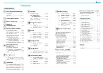
Technical section Rolling bearing structures and types Bearing fits Selection of bearing dimentions 5-5 Basic static load rating 5-6 Allowable axial load for 9-2 Tolerance and fit for shaft & housing Bearing internal clearance [Introduction of products, pamphlets and catalogs] Examples of bearing failures Bearing lubrication Specification tables 5-7 Applied calculation examples ...A 46 Boundary dimensions and bearing numbers 6-2 Dimensions of snap ring grooves Bearing tolerances 7- 2 Tolerance measuring method...A 80 Limiting speed 14 Shaft and housing design [Standard bearings] [Special purpose...
Open the catalog to page 5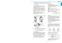
1. Rolling bearing structures and types 1-1 2) Rolling element Rolling elements may be either balls or rollers. Many types of bearings with various shapes of rollers are available. Ball Cylindrical roller (LW ² 3 DW)* Rolling bearings (bearings hereinafter) normally comprise bearing rings, rolling elements and a cage. (see Fig. 1-1) Rolling elements are arranged between inner and outer rings with a cage, which retains the rolling elements in correct relative position, so they do not touch one another. With this structure, a smooth rolling motion is realized during operation. Bearings are classified...
Open the catalog to page 6
1. Rolling bearing structures and types Radial ball bearing Deep groove ball bearing Angular contact ball bearing Radial bearing Bearings classified by use Single-row Matched pair or stack Four-point contact ball bearing Cylindrical roller bearing Single-row Needle roller bearing Rolling bearing Spherical roller bearing Thrust ball bearing Thrust bearing Thrust roller bearing Construction equipment Steel industry equipment Single direction with aligning seat race Single direction Tensioner bearing unit Double direction with aligning seat races Paper manufacturing equipment [Aircraft] Integral...
Open the catalog to page 7
Open type 1. Rolling bearing structures and types Table 1-2 Angular contact ball bearings Koyo Single-row Matched pair Contact sealed type With locating snap ring Suitable for ' extra-small or miniature .bearing , Back-to-back Face-to-face Tandem arrangement arrangement arrangement [pressed cage J [ machined cage J ■ The most popular types among rolling bearings, ■ Bearings with a flange or locating snap ring attached widely used in a variety of industries. on the outer ring are easily mounted in housings for ■ Radial load and axial load in both directions can simple positioning °f housing location....
Open the catalog to page 8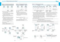
1. Rolling bearing structures and types \ Koyo Table 1-4 Self-aligning ball bearings Table 1-5 Cylindrical roller bearings Table 1-3 Four-point contact ball bearings Mainly use on rolling mill roll neck ■ Radial load and axial load in both directions can be accommodated. ■ A four-point contact ball bearing can substitute for a face-to-face or back-to-back arrangement of angular contact ball bearings. ■ Suitable for use under pure axial load or combined radial and axial load with heavy axial load. ■ This type of bearing possesses a contact angle (a) determined in accordance with the axial load...
Open the catalog to page 9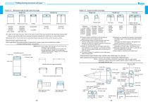
1. Rolling bearing structures and types Machined ring needle roller bearings With inner ring Without inner ring With inner ring Without inner ring n In spite of their basic structure, which is the same as that of NU type cylindrical roller bearings, bearings with minimum ring sections offer space savings and greater resistance to radial load, by using needle rollers. n Bearings with no inner rings function using heat treated and ground shafts as their raceway surface. [Recommended cage] Pressed cage [Main applications] Automobile engines, transmissions, pumps, power shovel wheel drums, hoists,...
Open the catalog to page 10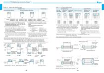
1. Rolling bearing structures and types Table 1-8 Spherical roller bearings Table 1-9 Thrust ball bearings Cylindrical bore Tapered bore Single direction Double direction Convex asymmetrical roller type Convex symmetrical roller type With flat back faces With spherical back face With aligning seat race With flat back faces With spherical back faces With aligning seat races ■ Spherical roller bearings comprising barrel-shaped convex rollers, double-row inner ring and outer ring are classified into three types : R(RR), RZ and RHA, according to their internal structure. ■ With the bearing designed...
Open the catalog to page 11All Koyo Seiko catalogs and technical brochures
 folder_srb
4 Pages
 folder_nrb
4 Pages
 bbu-cbr
2 Pages
 UK - UKX Series
2 Pages
 folder_agricon
2 Pages
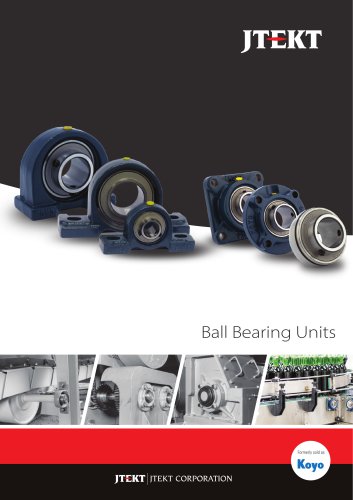 Ball Bearing Units
5 Pages