- Company
- Products
- Catalogs
- News & Trends
- Exhibitions
LED 25
1 /4Pages

LED 25
1 /4Pages
Catalog excerpts

As a fiber-optic probe that can be used for a wide range of applications, the LED 25 is a genuine innovation in the field of light measurement. For the first time ever, it is now possible to measure averaged LED intensity (ILED-A and ILED-B), illuminance and (using a goniometer) luminous flux with a single measurement head. At the same time, only a single calibration is required. Application Note Fiber-optic Probe for Averaged LED Intensity LED 25 as a fiber-optic probe for ILED-A and ILED-B measurements Single LEDs for the visible spectral range are typically described in terms of the following photometric quantities: luminous intensity IV , luminous flux F V, and the dominant wavelength. In the case of white LEDs, the ”correlated color temperature“ (CCT; unit: Kelvin) is usually stated. Since the luminous intensity is defined by the derivate dF/dW, the surface area of the detector should be as small as possible and the distance between the tip of the LED and the detector as large as possible. In general, such conditions can be set up only on a laboratory scale. For this reason, CIE publication 127 introduced the optical quantity of ‘averaged LED intensity‘ (ILED-A or ILED-B) for measuring single LEDs in 1997. According to this recommendation, a locally homogeneous detector with a surface area of 100 mm2 and V(l)-shaped spectral response should be positioned 316 mm or 100 mm (for ILED-A and ILED-B respectively) away from the tip of the LED to be measured. Fig. 1a: Measurement geometry for ILED-A and ILED-B Detector‘s surface area (100 mm2) Fig. 1b: LED 25 in combination with an ILED-B spacer tube and an LED mounted in a test socket Integrating sphere Since in most cases the tip of an LED does not correspond to the LED‘s point of light emission, ILED-A and ILED-B represent independent measurement quantities that are defined by the average illuminance at a specific distance from the respective light source multiplied by the square of this distance. ILED–A, B = Ev · r 2A,B Fig. 1a shows the basic measurement geometry, Fig. 1b a sectional drawing of the LED 25 in combination with an ILED-B spacer tube and an LED in a test fixture.
Open the catalog to page 1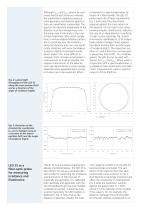
Although ILED-A and ILED-B cannot be compared directly with luminous intensity, the requirements regarding measurement geometry and detector specifications are nevertheless comparable: The spectral and absolute responsivity of the detector must be homogeneous over the entire area. Particularly in the case of high-brightness LEDs, which usually have a narrow-angled radiation pattern, this is crucial because the irradiance along the detector area can vary significantly. Detectors with poor homogeneity lead to slightly inconsistent results, which makes it far more difficult to compare them. To keep...
Open the catalog to page 2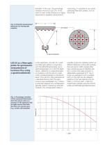
diameter. In this case, the percentage variation amounts to just 2%. In the event of even smaller distances or higher requirements regarding measurement uncertainty, it is possible to use cosineoptimized fiber-optic probes, such as the ISP 40. Fig. 4: Potential measurement geometry for testing LED modules Fig. 5: Percentage variation of the measured illuminance from the actual value as a function of the aperture ratio for light sources that take the form of a circular area (e.g. certain LED modules) In this application, the LED 25 is used as a fiber-optic probe in conjunction with the LEDGON...
Open the catalog to page 3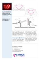
Fig. 6: Top: LED module as is used in traffic light systems Right: Examples of radiation patterns in the near field (top diagram) and the far field (bottom diagram) Fig. 7: Schematic drawing illustrating luminous flux measurement using the LED 25 and LEDGON For correct luminous flux measurement, it must be ensured that the angle scan of the LEDGON covers all directions in which light is emitted. The luminous flux is calculated from integration of the radiation pattern over the measured solid angle: Furthermore, the good cosine response of the LED 25 makes it possible to determine the luminous...
Open the catalog to page 4All Konica Minolta Sensing Americas catalogs and technical brochures
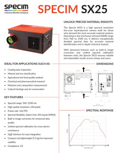 Specim SX25
2 Pages
 LumiTop Series
16 Pages
 LumiSuite
8 Pages
 CAS140D_IR
2 Pages
 CAS140CT_IR
8 Pages
 CAS125
4 Pages
 LumiCam 4000B_2400B_V2
12 Pages
 ISP Series
16 Pages
 DTS 140D NVIS
5 Pages
 ACS & ACU Series
12 Pages
 Spectrophotometer CM-36dG
8 Pages
 LGS 650
8 Pages
 LumiCam Series
16 Pages
 CAS 120
8 Pages
 CAS 140D
16 Pages
 New GM series gloss
4 Pages
 Spectrophotometer CM-5
3 Pages
 SPECTROPHOTOMETER CM-3700A
3 Pages
 CRI Illuminance Meter CL-70F
2 Pages
 Chroma Meter CS-150
3 Pages
 CHROMA METER CS-200
6 Pages
 Chroma Meter CL-200A
4 Pages
 2D Color Analyzer CA-2500
8 Pages
 Skin Analysis Software CM-SA
4 Pages
 GTI GLE-M
2 Pages
 GTI MiniMatcher Series
2 Pages
 Rhopoint TAMS™
6 Pages
 Rhopoint IQ FLEX 20
2 Pages
 Uni Gloss 60A/S/CT
4 Pages
 BC-10 Plus
4 Pages
 CR-410PB
4 Pages
 CR-400/410
5 Pages
 CM-3700A
3 Pages
 CM-700d/600d
3 Pages
 cm-25cg
2 Pages
 cm-m6
cm-m62 Pages
 DTS140 NVIS
6 Pages
 Rhopoint IQ-S
4 Pages
 RHOPTOINT instruments
6 Pages
 LumiCam 2400
4 Pages
 Medidor de Brillo 268A
4 Pages
 CM-25cG
4 Pages
 FD-9
FD-96 Pages
 RHOPOINT Flex 60 / Flex 20
2 Pages
 CR-20
CR-202 Pages
 CR-10 Plus
2 Pages
 CM-600D SPECTROPHOTOMETER
3 Pages
 ISP Series Integrating Spheres
17 Pages
 LCS IV
1 Page
 ISP40
ISP404 Pages
 LGS 1000
4 Pages
 LGS 350
8 Pages
 ISP 500
4 Pages
 ISP 2000
2 Pages
 ISP 150L
2 Pages
 ISP 1000
4 Pages
 LEDGON LED GONIOPHOTOMETER
4 Pages
 LED-81X/-850
4 Pages
 ACS-530
4 Pages
 LSM 350
4 Pages
 DTS 500 SPECTRORADIOMETER
8 Pages
 THE DTS 400 SYSTEM
2 Pages
 LUMICAM 1300
8 Pages
 CAS 140CTS
4 Pages
 MAS 40
8 Pages
 SPECTRO 320
12 Pages
 MM-4E CONTROLLED LIGHTING
2 Pages
 CR-410C Coffee
2 Pages
 Chlorophyll Meter SPAD-502
2 Pages
 MULTI GLOSS 268PLUS
2 Pages
 CM-SA SKIN ANALYSIS SOFTWARE
4 Pages
 CM-5 SPECTROPHOTOMETER
3 Pages


- Power supply unit
- DC power supply
- AC/DC power supply
- Digital imager
- Measuring device
- CMOS camera module
- Konica Minolta industrial camera
- LED lighting
- Analysis software solution
- Measuring machine
- Konica Minolta infrared camera
- Process software
- Windows software
- Real-time software
- Calibration system
- Single-output power supply
- Solids analyser
- Detection camera system
- Plastic cap
- Cylindrical cap