
Catalog excerpts
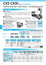
CKS-CKSF Series "Wish the Body Was a Little Thinner..." Is F:"ollw Key Features ■Very thin body Internal cylinders are located on the side toward workpiece, and which makes the motion of the cylinders parallel to jaw. These changes reduces thickness of the gripper by a half for use in confined spaces. ■Simple structure Direct drive mechanism to minimize hooking problem instead of worm drive mechanism. Motion failure caused by lack of grease can be also minimized. ■Large body type and hollow body type available ■Pushers (option) •Workpiece pushers can be additionally mounted (option) •3-point pusher for steady workpiece loading ■How to design external fingers to maximize dust-resistance ability •Please reduce the room between external finger and the gripper surface (as shown on the right) Model Size Quantity Option CKS-08AS with 2 of ET3 non-- contact reed switches and spring pusher (option) Symbol CKS CKSF Sensor, Quantity For option detail For external finger detail ■>2933 Specification Model
Open the catalog to page 1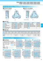
Internal Structure / Parts & Seals ■CKSF-16 to 50AS ■Parts List No. Performance Data ■Grip Force The graph shows grip force in opening and closing with effective external finger lengths £ from gripper cover surface under different air pressure (MPa) Open Closed 1 2 External Finger Length (cm) External Finger Length (cm) 1 2 External Finger Length (cm) External Finger Length (cm) External Finger Length (cm)
Open the catalog to page 2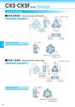
Thin Chuck Layout Drawing ■CKS-08AS (Optimal Grip Force 30N to 60N) ■CKS-16AS (Optimal Grip Force 100N to 250N) 5.5 width across flat ■CKS-12AS (Optimal Grip Force 50N to 130N) CKS-12AS 3 - M 3 × 0 . 5 depth 6 P. C. D. 48 120° (equally divided by 3) ■CKSF-16AS (Optimal Grip Force 100N to 250N) CKSF-16AS Standard through Hollow
Open the catalog to page 3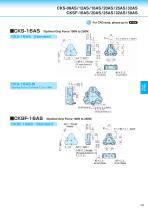
Thin Chuck Layout Drawing ■CKS-08AS (Optimal Grip Force 30N to 60N) ■CKS-16AS (Optimal Grip Force 100N to 250N) 5.5 width across flat ■CKS-12AS (Optimal Grip Force 50N to 130N) CKS-12AS 3 - M 3 × 0 . 5 depth 6 P. C. D. 48 120° (equally divided by 3) ■CKSF-16AS (Optimal Grip Force 100N to 250N) CKSF-16AS Standard through Hollow
Open the catalog to page 4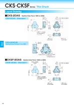
Thin Chuck Layout Drawing ■CKS-20AS (Optimal Grip Force 150N to 350N) ■CKS-25AS (Optimal Grip Force 300N to 650N) ■CKSF-20AS (Optimal Grip Force 150N to 350N) dia. ■CKSF-25AS (Optimal Grip Force 300N to 650N) through Hollow through Hollow depth 5 through 120° (equally divided by 3)
Open the catalog to page 5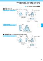
Thin Chuck Layout Drawing ■CKS-20AS (Optimal Grip Force 150N to 350N) ■CKS-25AS (Optimal Grip Force 300N to 650N) ■CKSF-20AS (Optimal Grip Force 150N to 350N) dia. ■CKSF-25AS (Optimal Grip Force 300N to 650N) through Hollow through Hollow depth 5 through 120° (equally divided by 3)
Open the catalog to page 6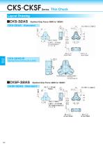
Thin Chuck Layout Drawing ■CKS-32AS (Optimal Grip Force 400N to 1000N) ■CKSF-50AS (Optimal Grip Force 1000N to 2500N) through Hollow depth 5 through 120°(equally divided by 3) ■CKSF-32AS (Optimal Grip Force 400N to 1000N) CKSF-32AS Standard depth 5 through Hollow depth 5 through 120°(equally divided by 3)
Open the catalog to page 7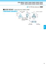
Thin Chuck Layout Drawing ■CKS-32AS (Optimal Grip Force 400N to 1000N) ■CKSF-50AS (Optimal Grip Force 1000N to 2500N) through Hollow depth 5 through 120°(equally divided by 3) ■CKSF-32AS (Optimal Grip Force 400N to 1000N) CKSF-32AS Standard depth 5 through Hollow depth 5 through 120°(equally divided by 3)
Open the catalog to page 8All Kondoh Seisakusho catalogs and technical brochures
-
HK
8 Pages
-
HF
8 Pages
-
HC
4 Pages
-
HA
4 Pages
-
BHGJ
4 Pages
-
HMA
6 Pages
-
QRD
2 Pages
-
QRB
2 Pages
-
RJX
2 Pages
-
RJE
2 Pages
-
WHB
2 Pages
-
HMD
4 Pages
-
BHE
8 Pages
-
BHG
6 Pages
-
QRC
2 Pages
-
QRA
8 Pages
-
RJFS
8 Pages
-
RJF
8 Pages
-
ZD(ZB)
6 Pages
-
WHF
4 Pages
-
WHA
4 Pages
-
HJD
4 Pages
-
HJQ
4 Pages
-
BHA
4 Pages
-
BSA
4 Pages
-
ZC(ZA) series
8 Pages
-
ZRA series
6 Pages
-
HJ series
6 Pages
-
LHA series
8 Pages


