
- Catalogs
- KOHLER POWER SYSTEMS
- Paralleling Switchgear


Paralleling Switchgear

Paralleling Switchgear
Kohler provides customized power systems that integrate generators, transfer switches, paralleling switchgear, and controllers to meet specific project requirements, ensuring seamless operation regardless of system complexity.
Paralleling multiple generators offers redundancy, efficiency, and flexibility, allowing for better space management, cost-effectiveness, and scalability for future growth.
Kohler's approach includes detailed planning, design, and testing to ensure reliable power systems. Their chart-based sequence of operation and intuitive user interface simplify system management.
Applications include emergency/standby power, single and dual utility systems, and peak shaving, each tailored to specific power needs with various operational modes.
The process involves controls that manage generator start-up, synchronization, load sharing, and generator management, ensuring voltage, frequency, and phase matching for seamless power transition.
Transition types include open and closed transfers, each with specific operational characteristics to suit different power transfer needs.
The document details the operation and configuration of KOHLER® paralleling switchgear systems, focusing on transition types, sequence of operation, response to abnormal conditions, operator interface, and system controls architecture.
The system can be configured for fast or soft (ramp) transfer. Fast transfer occurs within 100ms, while soft transfer allows for a user-adjustable kW/sec rate until the source reaches an unloaded setpoint, keeping the load energized during the transfer.
The sequence chart outlines steps from initial to final state, detailing the status of breakers and power buses, with a cross-reference to a response chart for abnormal conditions, ensuring clarity in system response and operator actions.
This chart provides system responses and operator actions if the system fails to respond correctly, including scenarios like breaker failures and generator issues, offering multiple operator actions to resolve faults.
The interface is user-friendly, providing intuitive navigation and clear information on system status and alarms, with features like alarm indications, system status, and navigation buttons for ease of use.
The architecture offers various levels of redundancy, from manual backup to redundant automation systems, with options for manual synchronization and parallel operation in case of touchscreen or PLC failures.
The PD-Series offers reliable solutions for various operational modes, with features like UL 891-listing, flexible design, and a range of breaker and power monitoring options.
The PD-Series is UL 1558-listed and complies with ANSI C37.20.1 standards, with bus ratings available through 9200 amps and a 200 kA withstand capability. Options for breaker trips and power monitoring are comprehensive, with the PD-4000 Series supporting up to 15 kV and including utility-grade protective relays.
Drawout breakers are standard, with UL 1066 drawout breakers for generator sets, utility, and distribution. NEMA 1 and NEMA 3R enclosures are available across all series. Short-circuit ratings vary, with up to 200 kA for PD-2000 and PD-3000, and 150 kA for PD-4000. Bus ratings range from 3000 A to 10,000 A depending on the series. Supports both 50 Hz and 60 Hz frequencies and can parallel up to 32 generators.
The KOHLER Decision-Maker Paralleling System (DPS) is suitable for simple paralleling applications, such as emergency standby generators. The system is highly configurable on-site and offers fast lead times. Key components include the KOHLER 6000 Controller, Master Control Panel, Power Distribution Switchboard, and Automatic Transfer Switch.
KOHLER provides extensive global support with over 800 locations offering sales, installation, and aftermarket services. Support is available 24/7 for troubleshooting, advice, and service needs.
For more information, contact KOHLER at 800.544.2444 or visit KohlerPower.com/Industrial.
Catalog excerpts
KOHLER Power Systems TOTAL SYSTEM INTEGRATION GENERATORS I TRANSFER SWITCHES I SWITCHGEAR I CONTROLS
Open the catalog to page 1
TOTAL SYSTEM INTEGRATION 2 THE BENEFITS OF PARALLELED POWER 4 TYPICAL PARALLELING APPLICATIONS 8 CHART-BASED SEQUENCE OF OPERATION 1 6 SYSTEM CONTROLS ARCHITECTURE 22 KOHLER. PD-SERIES PARALLELING SWITCHGEAR 24 DECISION-MAKER. PARALLELING SYSTEM 26
Open the catalog to page 2
YOUR JOB IS COMPLEX. WE MAKE IT EASY. At Kohler, there’s no such thing as a standard, one-size-fits-all power system – each one is unique. We know that the best system is the one that’s built to your project’s specific requirements. Your KOHLER power system is customized and built by a dedicated team of Kohler engineers. Total system integration means that no matter how large or complex, everything works together seamlessly – from generators and transfer switches to paralleling switchgear and controllers. ® Kohler has been a single-source supplier of complex power systems for decades. You know...
Open the catalog to page 4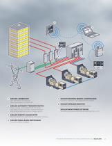
KOHLER® GENERATOR Gas generators 25-400 kW Diesel generators 10-3250 kW KOHLER AUTOMATIC TRANSFER SWITCH Open, closed and programmed-transition operating modes; standard, bypass-isolation and service-entrance switch configurations KOHLER DECISION-MAKER® CONTROLLERS Controls, monitors and diagnoses the system KOHLER WIRELESS MONITOR Performance monitoring around the clock KOHLER MONITORING SOFTWARE Monitors generators and transfer switches from a PC KOHLER REMOTE ANNUNCIATOR Remote monitoring and testing of transfer switches KOHLER PARALLELING SWITCHGEAR Low and medium voltage FOR MORE INFORMATION...
Open the catalog to page 5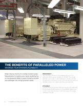
THE BENEFITS OF PARALLELED POWER MAXIMIZE YOUR SYSTEM’S FLEXIBILITY While it may be common for a facility to install a single large generator to meet its power needs, paralleling two or more generators offers a number of practical benefits and advantages over a single-generator system. REDUNDANCY The redundancy provided by the paralleling of two or more generators delivers greater reliability and flexibility than a single generator can provide. In critical applications, having more than one generator connected to the bus at all times ensures continuous generator power in the unlikely event that...
Open the catalog to page 6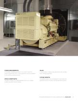
POWER REQUIREMENTS If the largest available generator is too small to meet the power requirements, two or more generators can be paralleled to provide the necessary power. SPACE CONSTRAINTS If space is limited and a large generator will not fit, multiple smaller generators can be utilized. VALUE In some cases, multiple small generators may cost less than one large generator. FUTURE GROWTH A paralleled system can be designed to add additional generators as your facility’s load requirements expand. FOR MORE INFORMATION OR TO FIND A DISTRIBUTOR, CALL 800.544.2444
Open the catalog to page 7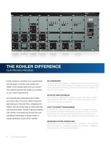
THE KOHLER DIFFERENCE OUR PROVEN PROCESS Kohler carefully considers your requirements and develops a solution that meets your needs. Every design starts with our proven, time-tested process that builds your system NO GUESSWORK Kohler’s chart-based sequence of operation eliminates the guesswork by detailing each step of every sequence. It clearly describes how the system works, what happens if there is a failure and the actions an operator can take to maintain power. to your exact requirements. Our experienced engineering team helps you every step of the way, determining and INTUITIVE USER INTERFACE...
Open the catalog to page 8
TYPICAL PARALLELING APPLICATIONS MATCH THE SYSTEM TO YOUR POWER NEEDS Kohler provides the system and operating modes that meet the needs of your facility, whether you require simple standby power or multiple-utility paralleling and emergency power, prime power or peak shaving. EMERGENCY / STANDBY The generators provide power in the event of a loss of utility service. Power transfer can take place at the transfer switch or by using the breakers in the switchgear. Figure 1 shows a typical ATS-based emergency/standby power system. The generator power is combined onto the paralleling bus. Power flows...
Open the catalog to page 10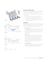
DUAL-UTILITY SYSTEM – RING Figure 4 shows a typical dual-utility system in which the utility bus and generator bus are separate lineups. The available sequence of operations is similar to the linear dual-utility system. The advantages of the ring dual-utility configuration over the linear configuration are: • The ability to feed the entire system with one utility feed without energizing the generator paralleling bus. • The ability to automatically respond to the generator’s main breakers failing to close and provide an alternate path to feed generator power to the load. PEAK SHAVE Peak shaving...
Open the catalog to page 11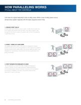
HOW PARALLELING WORKS IT’S ALL ABOUT THE CONTROLS Let’s look at a typical response to loss of utility power. When a loss of utility power occurs, almost every system responds with the basic sequence shown here. 1. ENGINE START DELAY A timer starts when there is a loss of utility. If utility returns before the timer expires, the system does not start. If the utility outage is long enough for the timer to expire, the system will commit to transferring to generator power. 2. START / START-UP LOAD SHED All available generators start. If the system is designed to supply power to loads as soon as one...
Open the catalog to page 12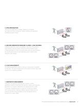
4. SYNCHRONIZATION The incoming generator’s voltage, frequency and phase are matched to the running bus. When matched, the generator paralleling breaker closes. 5. SECOND GENERATOR BREAKER CLOSES / LOAD SHARING Additional generator power is available to the load. The system’s load-sharing controls actively control the kW and KVAR output of each generator in order to proportionally share the load (maintain the same percent load on each generator) and maintain rated frequency and voltage. 6. LOAD MANAGEMENT As additional generators close to the bus, more power is available for the load. The load...
Open the catalog to page 13
HOW PARALLELING WORKS IT’S ALL ABOUT THE CONTROLS SYNCHRONIZATION Let’s take a detailed look at the synchronization process. The automatic synchronizer matches the incoming generator’s output (waveform) to the running bus. When the voltage, frequency and phase are all matched, the synchronizer will close the incoming generator’s breaker. PHASE MATCH The synchronizer adjusts the incoming generator’s speed to match the phase of the running bus. When matched, the two sine waves will be the same. Frequency Difference FREQUENCY MATCH The synchronizer adjusts the incoming generator’s speed to match...
Open the catalog to page 14All KOHLER POWER SYSTEMS catalogs and technical brochures
 33EFOZCJ
4 Pages
 13.5EFKOZD
4 Pages
 9EFKOZD
4 Pages
 5EFKOD
4 Pages
 200EOZDJ
4 Pages
 Global telecommunications
2 Pages
 Gas_Generators
12 Pages
 NFPA 110
2 Pages
 Power armor
6 Pages
 Automatic transfer switches
24 Pages
 Mobile generators
8 Pages
 Gas generators
8 Pages
 Industrial Power
24 Pages
 8RESVL
4 Pages
 Advanced Digital Control
2 Pages
 400REOZJ
4 Pages
 200 REOZJ F
4 Pages
 180 REOZJG
4 Pages
 20REOZDC
4 Pages
 40EORZDB
4 Pages
 Mobile Generator
4 Pages
 RXT series
6 Pages
 RDT series
6 Pages
 Full Mobile Line
4 Pages
 Commercial Marine Generators
4 Pages
 Marine Product Pocket Guide
16 Pages
 OnCue Brochure
2 Pages
 Telecom Brochure
2 Pages
 Gas Generators Brochure
4 Pages
 Towable GeneraTor
4 Pages
 Emergency Preparedness
8 Pages
 Enclosures / 20REOZJB
4 Pages
 Transfer Switches / KCT
8 Pages
 Transfer Switches / KCS
12 Pages
 Gas Generators / 30RZG
4 Pages
 Gas Generators / 25RZGB
4 Pages


- Diesel generator set
- Industrial genset
- Three-phase generator set
- 50 Hz generator set
- Stationary genset
- Soundproof generator set
- Water-cooled generator set
- Direct fuel injection generator set
- 60 Hz generator set
- Air-cooled generator set
- Single-phase generator set
- Emergency generator set
- Containerized generator set
- Mechanical fuel injection generator set
- Generator set with cover
- Outdoor generator set
- Gas generator set