- Catalogs
- Koganei Corporation
- Speed Controller with Dial Adjuster and Push Lock
Speed Controller with Dial Adjuster and Push Lock
1 /20Pages
Speed Controller with Dial Adjuster and Push Lock
1 /20Pages
Catalog excerpts
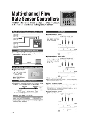
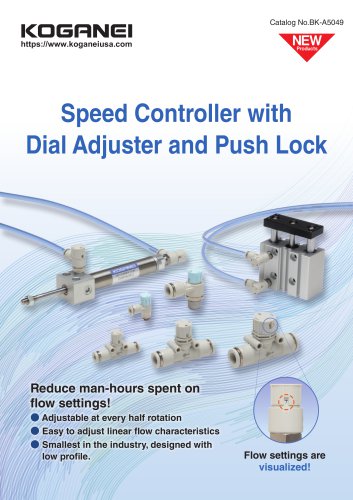
Speed Controller with Dial Adjuster and Push Lock Reduce man-hours spent on flow settings! ● Adjustable at every half rotation ● Easy to adjust linear flow characteristics ● Smallest in the industry, designed with low profile. Flow settings are visualiz
Open the catalog to page 1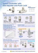
Speed Controller with Dial Adjuster and Push Lock Elbow Union straight Flow rate can be confirmed by the indicator. Indicators are located in 2 areas, side (upper/lower) and top. (*) Side dial upper window (Rotation count: 0.5, 1.5, 2.5…) *) Top dial is not available on the metric thread type of elbow or union straight φ4 mm [0.157 in.]. *) Dial indicator on union straight can be adjusted to face 360°. Compact design. World's smallest speed controller with dial. Rotation count and flow rate increase/decrease with proportional linear characteristics. Low flow rate types with micro-adjustments...
Open the catalog to page 2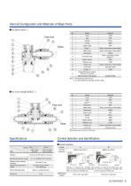
Internal Configuration and Materials of Major Parts ● For elbow (SCD□) Plastic body Brass, electroless nickel plated Metal body Brass, electroless nickel plated Threaded body HNBR Brass, electroless nickel platedNote 2 Elastic sleeve Release ring Guide ring Brass, electroless nickel plated Lock hook Stainless steel CollarNote 1 Tapered threads for pipes: Sealock processing Metric threads: With gasket Note 1: 04 thread size (R1/2) only. 2: For M3 thread size: Special stainless steel. ● For union straight (SSUD□) Dial cover Metal body Brass, electroless nickel plated Plastic body Elastic sleeve...
Open the catalog to page 3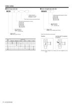
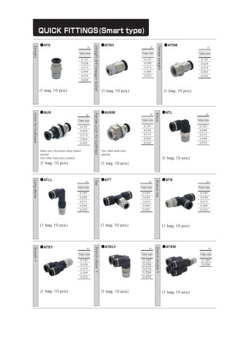
Order codes ● Elbow type with dial ● Union straight type with dial SSUD Control direction A: Meter-out control B: Meter-in control Flow rate typeNote Blank : Standard C : Low flow rate Flow rate typeNote Blank : Standard C : Low flow rate Fitting model SSUD: Union straight type with dial Fitting model SCD: Elbow type with dial Note: How to identify flow rate types Low flow rate (C is engraved on exterior) Screw size Tube size Remarks: Above diagram is for el
Open the catalog to page 4
Safety precautions (speed controllers with quick fittings) Before use, be sure to read the safety precautions. Before selecting and using an appropriate product, please read all the safety precautions carefully to ensure proper product use. The safety precautions described below are intended to help you use the product safely and correctly and to prevent injury to you or other people and damage to property. Always adhere to ISO4414 (Pneumatic fluid power - General rules and safety requirements for systems and their components), JIS B 8370 (Pneumatic fluid power - General rules relating to systems),...
Open the catalog to page 5
Safety precautions (speed controllers with quick fittings) ● Do not use the product near the ocean, in direct sunlight, near mercury vapor lamps, or near equipment that generates ozone. Deterioration of rubber parts caused by ozone may reduce performance and functions, or stop functions. (except for ozone-resistant products) ● Do not use media other than the ones listed in the specification table. Using a medium not listed in the specification table could lead to a short-term stoppage of functions, sudden degradation in performance, or reduced operating life. ● Do not use the product in the vicinity...
Open the catalog to page 6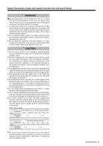
Safety Precautions (types with speed controller dial and quick fitting) WARNING ● Some products have control directions for the air, so check this text and the identifiers on the main unit before using them. There is a risk of causing personal injury or damage to the device if the control direction is mistaken. 1. To adjust the speed of an actuator, start with the needle almost closed and then gradually open it. The actuator may move abruptly as the needle is opened. Note that turning the adjustment knob clockwise closes the needle, and turning it counterclockwise opens it. 2. Do not adjust the...
Open the catalog to page 7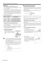
Handling instructions and precautions ● Installation Precautions for installing the main unit ● Connecting/disconnecting tubes Precautions for attaching tubes ① Use an appropriate tool on the hexagonal exterior of the ① Confirm that the cut ends of the tubes are cut at right angles, main unit to tighten it. ② W hen installing a threaded par t, tighten it to the recommended torque in the following table. Tightening it more than the tightening torque could damage the threads or deform the gasket, and cause leaks. Also, tightening it less than the recommended tightening torque could cause the...
Open the catalog to page 8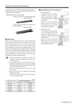
Handling instructions and precautions If removing pipes is difficult because the piping space is constricted, consult your nearest Koganei sales office for a specialized tool that is available. Specialized tool for removing tubes For φ3 [0.118], φ4 [0.157], and φ6 [0.236] tubes Order code: UJ-1 ● Speed adjustment for drive devices ① To increase speed T he speed of the drive device i n c re a s e s w h e n t h e s p e e d controller dial indicator is rotated counterclockwise from "0" (needle fully closed). W hen you reach the desired speed, be sure to lock it (press the adjustment knob) so that...
Open the catalog to page 9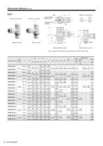
Release ring dimensions φZ Side dial position (window) Knob color: Light blue Knob color: Light gray Top dial position (window) note Meter-in control Meter-out control Tapered threads for pipes Note: Thread sizes M3 and M5 (metric threads) do not have a dial on top. B Tube Standard model diameter φD SCD(C)3-M3-□ SCD(C)3-M5-□ Release ring Width across Exterior diamflats X Y eter H φZ
Open the catalog to page 10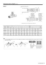
Top dial position (window) note ★ Control direction symbol Dimensions (Union straight) (mm [in.]) Side dial position (window) ★ Note: Tube size 4 (φ4 [0.157]) does not have a dial on top. Width across flats H Standard model ★ For union straight models, you can turn and adjust the orientation of the dial indicator 360° by using a wrench on the flat sides below the dial. Note: There are flat surfaces and curved surfaces, so be sure to put the wrench on the
Open the catalog to page 11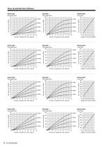
Flow characteristics (Elbow) Flow rate (L/min (ANR)) Flow rate (L/min (ANR)) Flow rate (L/min (ANR)) Flow rate (L/min (ANR)) Flow rate (L/min (ANR)) Flow rate (L/min (ANR)) Flow rate (L/min (ANR)) Flow rate (L/min (ANR)) Flow rate (L/min (ANR)) Flow rate (L/min (ANR)) Flow rate (L/min (ANR)) Flow rate (L/min (ANR))
Open the catalog to page 12All Koganei Corporation catalogs and technical brochures
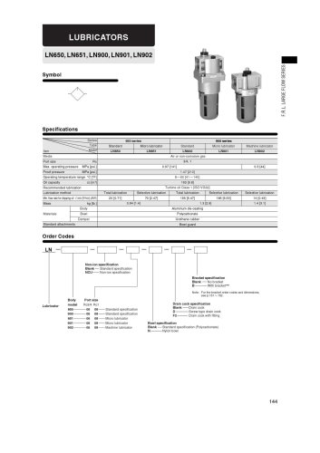 LUBRIFICATION
1 Page
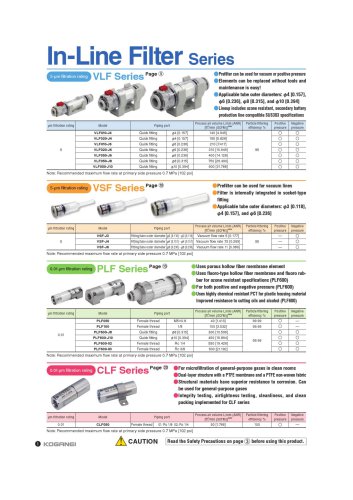 In -Line Filter Series
1 Page
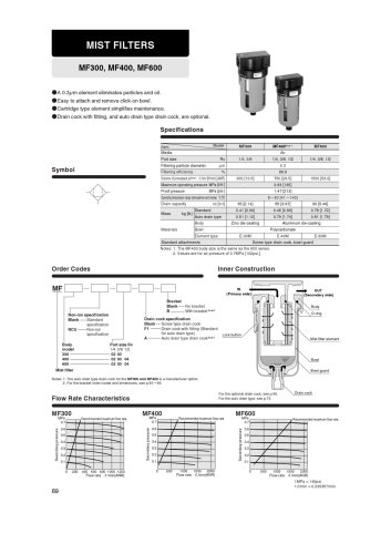 MIST FILTERS
1 Page
 MANIFOLD REGULATORS
1 Page
 PRECISION REGULATOR
1 Page
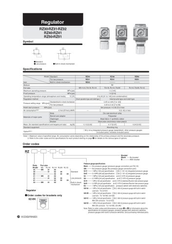 Regulator
1 Page
 EXHAUST FILTERS
1 Page
 Air filter
1 Page
 FILTER REGULATORS
1 Page
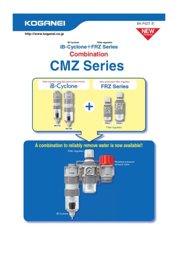 CMZ Series
1 Page
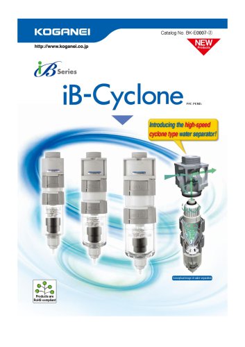 IB Cyclone
1 Page
 IB ZERO
1 Page