NRM
1 /12Pages

NRM
1 /12Pages
Catalog excerpts

Non-Contact Radar Level Transmitter monitoring • analysing Process connection: BSP, NPT, pipe coupling, Tri-Clamp®, flange M aterial: PP, aluminium, stainless steel High temperature version Approval: ATEX, IECEx (Ex ia) Integrated version Stainless steel housing Parabolic antenna KOBOLD companies worldwide: AUSTRALIA, AUSTRIA, BELGIUM, BULGARIA, CANADA, CHINA, CZECHIA, EGYPT, FRANCE, GERMANY, GREAT BRITAIN, HUNGARY, INDIA, INDONESIA, ITALY, MALAYSIA, MEXICO, NETHERLANDS, PERU, POLAND, Republic of Korea, ROMANIA, RUSSIA, SPAIN, SWITZERLAND, THAILAND, TUNISIA, turkey, USA, VIETNAM KOBOLD Messring GmbH Nordring 22-24 D-65719 Hofheim/Ts. Head Office: +49(0)6192 299-0 +49(0)6192 23398 [email protected] www
Open the catalog to page 1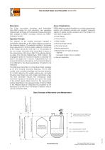
Non-Contact Radar Level Transmitter Model NRM Description The 2-wire non-contact microwave level transmitters type NRM provide the most advanced, new generation measurement technique of the industrial process automation field, available as NRM-4 (compact version) and NRM-7 (integrated version). Operation Principle The reflection of the emitted microwave impulses is considerably depending on the relative dielectric constant of the measured medium. The essential condition of microwave level measurement is that the relative dielectric constant (εr) of the medium should be more than 1.9. The operation...
Open the catalog to page 2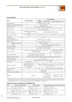
Non-Contact Radar Level Transmitter Model NRM Technical Details Compact (NRM-4) Type Plastic housing Measured values Metal housing High temperature version level, distance, volume, mass Frequency of measurement signal Measuring range 0.2 -23 m see »Measuring ranges« page 4 <0.5 m: ±25 mm, 0.5-1m: ±15 mm, 1–1.5 m: ±10 mm, 1.5–8 m: ±3 mm, >8 m: ±0.04% of the measured distance Linearity error* 11° depending on the antenna type Min. beam angle Min. εr of the medium 6° depending on the antenna type 1.9 depending on the meas. range 1.4 depending on the meas. range, see »Measuring ranges« page 4 Temperature...
Open the catalog to page 3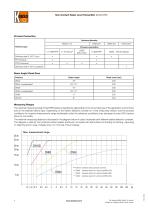
Non-Contact Radar Level Transmitter Model NRM Process Connection Antenna diameter DN40 (1½") Antenna type Process connection 1½" BSP/NPT Stainless steel (1.4571) horn PTFE enclosure Stainless steel (1.4571) parabolic Beam Angle / Dead Zone Antenna Beam angle Measuring Ranges The maximal measuring range of the NRM radars is significantly depending on the circumstances of the application environment and on the selected device type. Depending on the relative dielectric constant εr of the measuring medium and the process conditions the maximal measurement range (achievable under the reference conditions)...
Open the catalog to page 4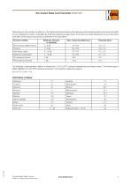
Non-Contact Radar Level Transmitter Model NRM Depending on the process conditions or the plastic antenna enclosure the following typical reducing factors are recommended to be considered in order to calculate the maximal measuring range. When more than one reducing factors occur at the same time then all the factors should be considered for the calculation: Process condition Reflection reduction in amplitude Reducing factor Slow mixing or slightly waving Fast mixing, vortex Steaming, condensation PTFE antenna enclosure For example: measurement medium is styrene (εr= 2.4) at 25 process temperature...
Open the catalog to page 5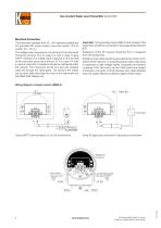
Non-Contact Radar Level Transmitter Model NRM Electrical Connection The instrument operates from 20 ... 36 V galvanic isolated and not grounded DC power supply in two-wire system. (For Ex version: 20 ... 30 VDC! The voltage value measured on the terminal of the instrument should be minimum 20 V (in case of 4 mA)! In case of using HART® interface The voltage value measured on the terminal of the instrument should be minimum 20 V (in case of 4 mA)! In case of using 250 Ω resistance should be maintained within the network. The instrument should be wired with shielded cable led through the cable...
Open the catalog to page 6
Non-Contact Radar Level Transmitter Model NRM Wiring diagram integrated version (NRM-7) Prior to wiring ensure that the power supply is turned off at the source. (For wiring the unit 6 x 0,5 mm2 cross section or greater cable is recommended). The necessary programming can be made after energising the unit. Colour codes Green – Yellow – White – I (+) Positive point of current loop measurement (-) egative point of current loop measurement N (-) egative point of current loop, power supply N and HART® Brown – I (+) ositive point of current loop, power supply P and HART® Green/Yellow – GND Grounding...
Open the catalog to page 7
Non-Contact Radar Level Transmitter Model NRM Order Details Compact Version (Example: NRM-4 A P R80 00 0) Model Antenna / measuring range Material antenna / housing Process connection Output / version / approval R80 = BSP R8P2) = SP connection with B PP enclosure R8T2) = SP connection with B PTFE enclosure N80 = NPT N8P2) = PT connection with N PP enclosure M = 1.4571/PBT S = 1.4571/ aluminium (coated) K = 1.4571/ stainless steel N8T2) = PT connection with N PTFE enclosure T9T2) = Tri-Clamp® 2" connection (1.4571) with PTFE enclosure C9T2) = ipe coupling DN50 p with (1.4571) PTFE enclosure R90...
Open the catalog to page 8
Non-Contact Radar Level Transmitter Model NRM Order Details Integrated Version (Example: NRM-7 A P R80 P0 0) Model Antenna / measuring range Material antenna / housing Process connection Output / version / approval R80 = BSP R8P1) = SP connection with B PP enclosure B R8T1) = SP connection with PTFE enclosure N80 = NPT N N8P1) = PT connection with PP enclosure N N8T1) = PT connection with PTFE-enclosure P = PP/PBT 1) 4) T9T1) = Tri-Clamp® 2" connection (1.4571) with PTFE enclosure p C9T1) = ipe coupling DN50 (1.4571) with PTFE enclosure R90 = BSP R9P1) = SP connection with B PP enclosure B R9T1)...
Open the catalog to page 9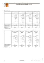
Non-Contact Radar Level Transmitter Model NRM Plastic housing 2" horn antenna Material of wetted parts Plastic housing 1½" horn antenna Aluminium housing 2" horn antenna Aluminium housing 1½" horn antenna Process connection Aluminium housing 1½" antenna with PP enclosure Plastic housing 1½" PP encapsulated antenna Aluminium housing 2" antenna with PP enclosure Plastic housing 2" PP encapsulated antenna Dead zone Lmin* * Under reference conditions Material of wetted parts Dead zone Lmin* Process connection
Open the catalog to page 10All KOBOLD Messring GmbH catalogs and technical brochures
 DMH
DMH7 Pages
 DON
DON11 Pages
 Product summary Kobold Messring
44 Pages
- Flowmeter
- Volume flow monitor
- Liquid flow monitor
- Data logger
- Level limit switch
- Pressure gauge
- Waterproof flow meter
- Liquid level detector
- Gas flow monitor
- Level probe
- Temperature datalogger
- Stainless steel flow monitor
- Liquid level sensor
- Digital pyrometer
- Industrial flow monitor
- Analog pressure gauge
- Pressure probe
- Industrial thermometer
- USB datalogger
- In-line flow meter