MIM
1 /10Pages

MIM
1 /10Pages
Catalog excerpts
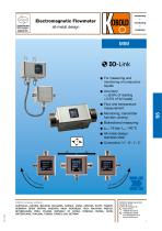
Electromagnetic Flowmeter all-metal design Accuracy: < ± (0.8% of reading + 0.5% of full scale) Monitoring, transmitter function, dosing Bidirectional measuring All-metal design: stainless steel F or measuring and monitoring of conductive liquids KOBOLD companies worldwide: AUSTRALIA, AUSTRIA, BELGIUM, BULGARIA, CANADA, CHINA, CZECHIA, EGYPT, FRANCE, GERMANY, GREAT BRITAIN, HUNGARY, INDIA, INDONESIA, ITALY, MALAYSIA, MEXICO, NETHERLANDS, PERU, POLAND, Republic of Korea, ROMANIA, RUSSIA, SPAIN, SWITZERLAND, THAILAND, TUNISIA, turkey, USA, VIETNAM KOBOLD Messring GmbH Nordring 22-24 D-65719 Hofheim/Ts. Head Office: +49(0)6192 299-0 +49(0)6192 23398 info.de@kobold.
Open the catalog to page 1
Electromagnetic flowmeter in all-metal design Model MIM Description The new flowmeter MIM was developed for measuring and monitoring smaller- and medium-sized flow of conductive liquids in pipes. The device operates according to the electromagnetic measurement principle. According to Faraday's Law of magnetic induction, a voltage is induced in a conductor moving through a magnetic field. The electrically conductive measuring agent acts as the moved conductor. The voltage induced in the measuring agent is proportional to the flow velocity and is therefore a value for the volumetric flow. The flowing...
Open the catalog to page 2
Electromagnetic flowmeter in all-metal design Model MIM Technical Details (continued) Electrical connection: plug M12x1,4-pin Environmental testing Sh0ck resistance DIN EN 60068-2-30:2006: severity level b lO-Link specification Manufacturer ID: Manufacturer name: IO-Link specification: Bitrate: Minimal cycle time: SIO-Mode: Block parameterisation: Operational readiness: Max. cable length: 1105 (decimal), 0 x 0451 (hex) Kobold Messring GmbH V1.1 COM3 1,1 ms yes (OUT1 in configuration IO-Link) yes 10 s 20 m No responsibility taken for errors; subject to change without prior notice.
Open the catalog to page 3
Electromagnetic flowmeter in all-metal design Model MIMOrder Details (Example: MIM-12 15H G5 C3T 0)Model MIM-12 = housing/ electrode VA, FKM seal MIM-134) = housing/ electrode VA, EPDM seal Electronics Special version C3T = compact, TFT display, 2 outputs (current/voltage/ pulse/frequency/alarm output configurable), M12x1 plug P023) = remote version, TFT display, 2m PVC cable, max. 85 °C E023) = remote version, TFT display, 2m ETFE cable, max. 140 °C 0 = without K5)= including calibration report 11 l/min-package (nameplate (l/min or ml/min, °C, bar)), calibrated range and temperature °C 2) GPM-package...
Open the catalog to page 4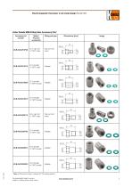
Electromagnetic flowmeter in all-metal design Model MIM Order Details MIM Fitting Sets Accessory Kits* Meter / Process connection * Note: All fitting kits include 2 x Klinger SIL® flat sealing gaskets No responsibility taken for errors; subject to change without prior no
Open the catalog to page 5
Electromagnetic flowmeter in all-metal design Model MIM Order Details MIM Fitting Sets Accessory Kits* (continued) G 2 female/ Adapter 50 2" Tri-Clamp® Tri-Clamp® 2" Meter / Process connection No responsibility taken for errors; subject to change without prior notice. * Note: All fitting kits include 2 x Klinger SIL® flat sealing gaskets or 2 x FKM O-
Open the catalog to page 6
Electromagnetic flowmeter in all-metal design Model MIM (3 (4 (5 (6 a No responsibility taken for errors; subject to change without prior notice.
Open the catalog to page 7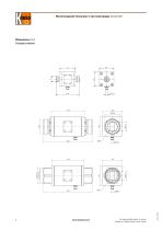
Electromagnetic flowmeter in all-metal design Model MIM Dimensions [mm] Compact version No responsibility taken for errors; subject to change without prior notice.
Open the catalog to page 8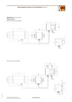
Electromagnetic flowmeter in all-metal design Model MIM Dimensions [mm] (continued) Remote version Without wall mounting brackets With wall mounting brackets No responsibility taken for errors; subject to change without prior notice.
Open the catalog to page 9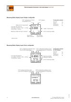
Electromagnetic flowmeter in all-metal design Model MIMMeasuring Mode, Display Layout »Single« configurable OUT1 configured as 4-20 mA and assigned to flow Configurable variables Display area for output status Font white: MV* within FS Font yellow: 100% FS <= MV* <= OvFlow Font red: MV* > OvFlow Measuring variable with sign for direction 4 digits + decimal point Unit for measuring variable INFO Key symbol 1 Key symbol 2 (Menu functions) (Options INFO) * Measured Value OUT1 configured as switching output OUT2 configured as analogue output Push-Pull and assigned flow 4-20 mA and assigned to temperature...
Open the catalog to page 10All KOBOLD INSTRUMENTATION catalogs and technical brochures
 PSD
PSD7 Pages
 RFS
RFS2 Pages
 KES
KES7 Pages
 MIK
MIK7 Pages
 DWF
DWF4 Pages
 ATA-K
ATA-K4 Pages
 HND-F
HND-F7 Pages
 AFK-G2
3 Pages
 HND-C
HND-C3 Pages
 ACM-1
ACM-16 Pages
 HND-R
HND-R4 Pages
 APM-1
APM-16 Pages
 HND-T120
10 Pages
 MWD
MWD21 Pages
 TNF
TNF6 Pages
 TNS
TNS6 Pages
 TWP
TWP4 Pages
 TDD-1
TDD-13 Pages
 TWR
TWR2 Pages
 TSA
TSA2 Pages
 TRS
TRS2 Pages
 M
M23 Pages
 NSV
NSV4 Pages
 NIR-9
NIR-95 Pages
 MM
MM13 Pages
 NGM
NGM10 Pages
 NUS-4
NUS-45 Pages
 NMF
NMF4 Pages
 NGR
NGR7 Pages
 PLS
PLS2 Pages
 PAS
PAS22 Pages
 NWS
NWS5 Pages
 NVI
NVI3 Pages
 NV
NV2 Pages
 NTB
NTB3 Pages
 NSC
NSC4 Pages
 NMT
NMT2 Pages
 NMC
NMC4 Pages
 NKP
NKP2 Pages
 NGS
NGS8 Pages
 NES
NES2 Pages
 NEC
NEC6 Pages
 NCW
NCW4 Pages
 NBK
NBK5 Pages
 LNM
LNM2 Pages
 PUM
PUM2 Pages
 HND-P105
8 Pages
 SEN-96
3 Pages
 MAN-RF...M21..DRM-602
4 Pages
 MAN-SD
4 Pages
 SEN-86 AUF
6 Pages
 SEN-3251 / 3252
3 Pages
 SCH
SCH21 Pages
 PMP
PMP2 Pages
 PAD
PAD23 Pages
 DAK-1
DAK-16 Pages
 DAT-1
DAT-16 Pages
 DKB
DKB3 Pages
 DKF
DKF2 Pages
 DAA
DAA2 Pages
 DAR
DAR6 Pages
 DON-...LCD
10 Pages
 EPS
EPS7 Pages
 BGN
BGN6 Pages
 TSK
TSK6 Pages
 DUC
DUC13 Pages
 VKP
VKP2 Pages
 VKM
VKM7 Pages
 VKG
VKG7 Pages
 URM
URM4 Pages
 URK
URK4 Pages
 TMU
TMU13 Pages
 TME
TME8 Pages
 SMV
SMV10 Pages
 PSR
PSR5 Pages
 PPS
PPS2 Pages
 PIT
PIT11 Pages
 PEL-L
PEL-L4 Pages
 KSM
KSM4 Pages
 KDF/KDG
4 Pages
 KAL-D
KAL-D3 Pages
 DVH / DVE
8 Pages
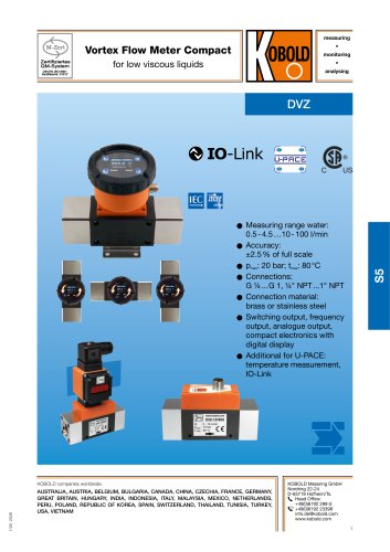 Vortex Flow Meter Compact
9 Pages
 DVK
DVK6 Pages
 DUK-C
DUK-C7 Pages
 KSR/SVN
2 Pages
 DSV-3
DSV-34 Pages
 DRH AUF
6 Pages
 DPL-F
DPL-F4 Pages
 DPE-F
DPE-F5 Pages
 DOT
DOT5 Pages
 DMS
DMS4 Pages
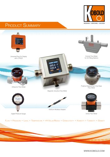 Product Summary
44 Pages
 DON
DON13 Pages


- Flowmeter
- Temperature probe
- Volume flow monitor
- Liquid flow monitor
- Resistance temperature sensor
- Pressure transmitter
- Level limit switch
- Pressure gauge
- Analog pressure transmitter
- Waterproof flow meter
- Liquid level detector
- Gas flow monitor
- Level probe
- Stainless steel flow monitor
- Digital pyrometer
- Liquid level sensor
- Pressure switch
- Industrial flow monitor
- Analog pressure gauge
- Pressure probe