WK73
1 /2Pages
WK73
1 /2Pages
Catalog excerpts
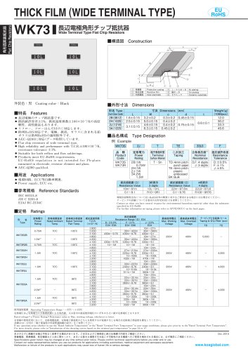
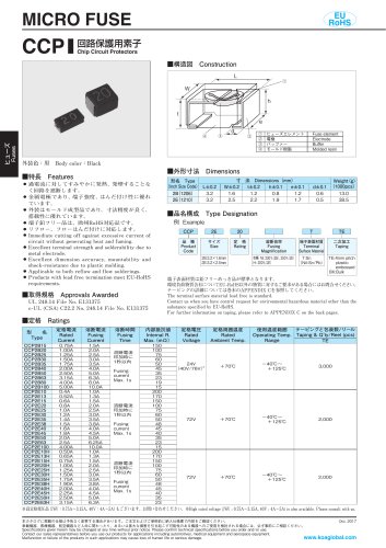
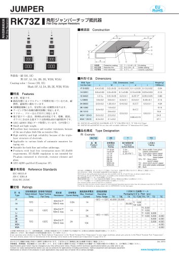
角形面実装抵抗器 Flat Chip Resistors THICK FILM (WIDE TERMINAL TYPE) 長辺電極角形チップ抵抗器 Wide Terminal Type Flat Chip Resistors 外装色黒 Coating colorBlack 頼性、高性能品もあります。 リ フロー、フローはんだ付けに対応します。 ● 州RoHS対応です。電極、抵抗、ガラスに含まれる鉛 欧 ガラスは欧州RoHSの適用除外です。 ● EC-Q200に対応 A データ取得 しています。 ● lat chip resistors of wide terminal type. F −6 ● igh reliability and performance with T.C.R.±100×10 /K, H resistance tolerance ±1%. ● uitable for both reflow and flow solderings. S ● roducts meet EU-RoHS requirements. P U-RoHS regulation is not intended for Pb-glass E contained in electrode, resistor element and glass. ● EC-Q200 qualified. A ● 電 源回路、ECU等自動車関連。 P ower supply, ECU etc. IEC 60115-8 JIS C 5201-8 EIAJ RC-2134C 定格周囲温度 Rated Ambient Temp. 定格端子部温度 Rated Terminal Part Temp. ■品名構成 Type Designation 例 Example WK73S 端子表面材質 二次加工 Terminal Taping Surface Material TD: 4mm pitch TSn punch paper TE: 4mm pitch plastic embossed BK: Bulk 3桁表示 3 digits 10L〜91L R10〜9R1 公称抵抗値※1 Nominal Resistance D,F : 4 digits J : 3 digits 抵抗値許容差 Resistance Tolerance D:±0.5% F :±1% J :±5% 抵抗値範囲 Ω Resistance Value 22m〜97.6m 0.1〜9.76 環境負荷物質含有についてEU-RoHS以外の物質に対するご要求がある場合にはお問合せください。 テーピングの詳細については巻末のAPPENDIX Cを参照してください。 Contact us when you have control request for environmental hazardous material other than the substance specified by EU-RoHS. For further information on taping, please refer to APPENDIX C on the back pages. ■定格 Ratings 定格電力 Power Rating 抵抗値範囲 Ω Resistance Value 10m〜91m 0.1〜9.1 ■参考規格 Reference Standards 形 名 Type 最高使用電圧 Max. Working Voltage 最高過負荷電圧 Max. Overload Voltage テーピングと包装数/リ ール Taping & Q’ ty/Reel pcs 使用温度範囲 Operating Temperature Range−55℃〜155℃ 定格電圧
Open the catalog to page 1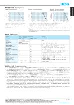
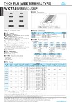
端子部温度 Terminal part temperature 端子部温度 Terminal part temperature WK73S2B 1WWK73S/R3A 、 2W 周囲温度70℃以上で使用される場合は、上図負荷軽減 曲線に従って、定格電力を軽減してご使用ください。 For resistors operated at an ambient temperature of 70℃ or above, a power rating shall be derated in accordance with the derating curve. ・ 記の端子部温度以上で使用される場合は、 上 負荷軽減曲線に従って定格電力を軽減してご使用く さ だ い。 ・ 1の定格電力で使用される場合は右側の端子部温度によ ※ る負荷軽減曲線を ご使用く さ だ い。 ・ ご使用方法につき しては巻頭の ま “端子部温度の負荷軽減曲線の紹介” を参照願います。 ・ or resistors operated terminal part temperature of described for each size or above, a power rating shall be F derated in accordance with derating curve. ・ f you want...
Open the catalog to page 2All KOA catalogs and technical brochures


Archived catalogs
- Bourn And Koch temperature sensor
- Bourn And Koch resistance temperature sensor
- Compact temperature probe
- Wire-wound resistor
- Board-mount resistor
- Power resistor
- Housed resistor
- Thin-film resistor
- Bourn And Koch thermistor
- SMD resistor
- Platinum resistive temperature sensor
- RoHS resistor
- Thick-film resistor
- Thin-film temperature sensor
- Voltage resistor
- High-power resistor
- High-voltage resistor
- Miniature fuse
- NTC thermistor
- SMD fuse