SG73S
1 /2Pages

SG73S
1 /2Pages
Catalog excerpts
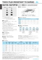
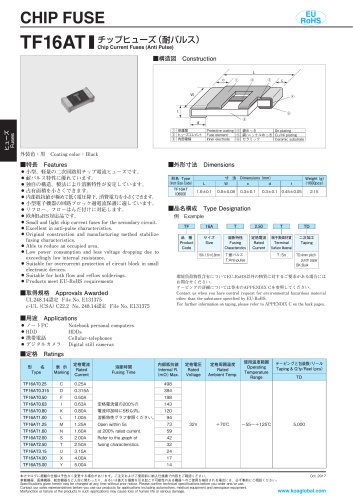
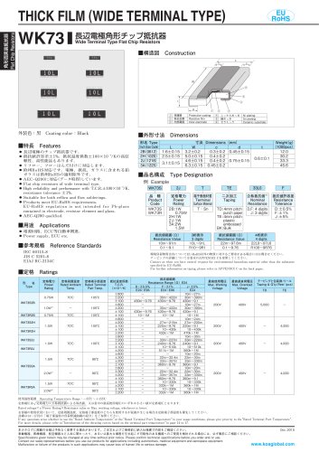
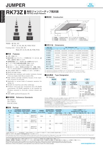
角形面実装抵抗器 Flat Chip Resistors THICK FILM (RESISTANT TO SURGE) 耐サージチップ抵抗器 SG73S Endured Surge Voltage Flat Chip Resistors 耐パルスチップ抵抗器 SG73P Endured Pulse Power Flat Chip Resistors ■構造図 Construction 形名 Type Inch Size Code チップ抵抗器 RK73 と比較してサージ耐圧とパルス耐圧に 優れています。 ● 抵抗値許容差±0.5に対応します。 データ取得 しています。 ● Superior to RK73 series chip resistors in surge withstanding voltage and pulse withstanding voltage. ● Resistance tolerance is available from ±0.5. ● Suitable for both reflow and flow solderings. ● Products with lead free termination meet EU-RoHS requirements. EU-RoHS regulation is not intended for Pb-glass contained in electrode, resistor element and glass. ● AEC-Q200 qualified. ■品名構成 Type Designation 例 Example SG73S 定格電力 Power Rating 端子表面材質 Terminal Surface Material 二次加工 Taping 公称抵抗値 Nominal Resistance 抵抗値許容差 Resistance Tolerance TP:2mm pitch punch paper TD:4mm pitch punch paper TE:4mm pitch plastic embossed BK:Bulk ● Circuits to catch inductive lighting surge. 端子表面材質は鉛フリーめっき品が標準となります。 環境負荷物質含有についてEU-RoHS以外の物質に対するご要求がある場合にはお問合せください。 テーピングの詳細については巻末のAPPENDIX Cを参照してください。 The terminal surface material lead free is standard. Contact us when you have control request for environmental hazardous material other than the substance specified by EU-RoHS. For further information on taping, please refer to APPENDIX C on the back pages. ■参考規格 Reference Standards IEC 60115-8 JIS C 5201-8 EIAJ RC-2134C 定格電力 Power Rating 定格周囲温度 定格端子部温度 抵抗温度係数 Rated Rated T.C.R. Ambient Terminal ×10−6/K Temp. Part Temp. 抵抗値範囲 Resistance RangeΩ 最高使用電圧 Max. Working Voltage 最高 過負荷電圧 Max. Overload Voltage 二次加工と包装数/リール Packaging & Q’ ty/Reelpcs TP 使用温度範囲 Operating Temperature Range−55℃〜155℃ 定格電圧は √‾ 定格電力×公称抵抗値によ
Open the catalog to page 1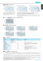
端子部温度 Terminal part temperature 端子部温度 Terminal part temperature 周囲温度70℃以上で使用される場合は、左図負荷軽減曲線 に従って、定格電力を軽減して御使用ください。 For resistors operated at an ambient temperature of 70℃ or above, a power rating shall be derated in accordance with derating curve on the left. 上記の端子部温度以上で使用される場合は、負荷軽減曲線に従って定格電力を軽減してご使用ください。 ※2の定格電力で使用される場合は右側の端子部温度によ る負荷軽減曲線を ご使用く さ だ い。 ※ 使用方法につきましては巻頭の“端子部温度の負荷軽減曲線の紹介”を参照願います。 ご For resistors operated terminal part temperature of described for each size or above, a power rating shall be derated in accordance with derating curve. If you want to use at the rated power of ※2, please...
Open the catalog to page 2All KOA catalogs and technical brochures


Archived catalogs
- Bourn And Koch temperature sensor
- Bourn And Koch resistance temperature sensor
- Compact temperature probe
- Wire-wound resistor
- Board-mount resistor
- Power resistor
- Housed resistor
- Thin-film resistor
- Bourn And Koch thermistor
- SMD resistor
- Platinum resistive temperature sensor
- RoHS resistor
- Thick-film resistor
- Thin-film temperature sensor
- Voltage resistor
- High-power resistor
- High-voltage resistor
- Miniature fuse
- NTC thermistor
- SMD fuse