

RK73H

RK73H
1. Product Overview and Construction
The RK73H series consists of precision-grade flat chip thick film resistors. They feature a metal glaze thick film resistive layer for excellent heat and weather resistance. The electrodes have a triple-layer structure ensuring high stability and reliability. The resistors are small, lightweight, and compatible with various automatic mounting machines and soldering methods (flow and reflow). Lead-free terminations comply with EU RoHS, except for Pb-glass in electrodes and resistive elements, which are exempt.
Construction includes a ceramic alumina substrate, resistive film, inner electrode, nickel plating, solder plating, and protective coating. Coating colors vary by type: black or blue.
2. Features
- Small size and light weight.
- Metal glaze thick film for superior heat and weather resistance.
- Triple-layer electrode structure for enhanced stability and reliability.
- Compatible with automatic mounting and soldering processes.
- Lead-free terminations meeting EU RoHS standards.
- AEC-Q200 qualification for automotive applications (except 1F type).
3. Reference Standards
Compliance with IEC 60115-8, JIS C 5201-8, and EIAJ RC-2134C standards.
4. Type Designation and Dimensions
Types are designated by size codes (e.g., 1F, 1H, 1E, 1J, 2A, 2B, 2E, W2H, W3A) with detailed dimensions in millimeters and weights per 1000 pieces. Power ratings range from 0.03W (1F) up to 1W (W3A). Terminal surface materials include Sn (standard), Au (gold plated available for some types), and Sn/Pb (limited availability).
5. Electrical Ratings and Performance
| Type | Power Rating | Rated Ambient Temp. | Rated Terminal Temp. | T.C.R. (×10⁻⁶/K) | Resistance Range (Ω) | Max Working Voltage | Max Overload Voltage |
|---|---|---|---|---|---|---|---|
| 1F | 0.03W | 70℃ | — | ±200 | 100k–1M | 20V | 30V |
| 1H | 0.05W | 70℃ | — | ±200 | 10–10M | 25V | 50V |
| 1E | 0.1W | 70℃ | 125℃ | ±100 | 10–1M | 50V | 100V |
| 1J | 0.1W | 70℃ | 125℃ | ±100 | 1.02k–1M | 75V | — |
| 2A | 0.25W | 70℃ | 125℃ | ±100 | 10–1M | 150V | 200V |
| 2B | 0.25W | 70℃ | 125℃ | ±100 | 10–1M | 200V | 400V |
| 2E | 0.5W | 70℃ | 125℃ | ±100 | 10–1M | — | — |
| W2H | 0.75W | 70℃ | 125℃ | ±100 | 10–1M | — | — |
| W3A | 1W | 70℃ | 125℃ | ±100 | 10–1M | 200V (500V*) | 400V (500V*) |
*Consult manufacturer for values in parentheses.
6. Derating Curves
Power rating must be derated when operating above 70℃ ambient temperature or above specified terminal part temperatures. Derating curves are provided to guide reduction of rated power to ensure reliability under elevated temperature conditions.
7. Performance and Reliability Tests
- Resistance Accuracy: Within specified tolerance at 25℃.
- Temperature Coefficient of Resistance (T.C.R.): Within specified limits measured between +25℃/−55℃ and +25℃/+125℃.
- Overload (Short Time): Rated voltage ×2.5 (or ×2 for 1E and 2B) applied for 5 seconds.
- Solder Heat Resistance: 260℃ ±5℃ for 10 seconds.
- Rapid Temperature Change: 100 cycles between −55℃ and +125℃.
- Moisture Resistance: 1000 hours at 40℃, 90–95% RH with ON/OFF cycling.
- Endurance at 70℃: 1000 hours with ON/OFF cycling.
- High Temperature Exposure: 1000 hours at +125℃ (1F) or +155℃ (others).
8. Precautions for Use
- The alumina substrate has a different thermal expansion coefficient than mounting boards, which may cause solder joint cracks under repeated thermal cycling or load ON/OFF cycles, especially for larger W2H and W3A types.
- Design considerations should include pad size, solder volume, and board heat dissipation to minimize crack risk.
- RK73H1F type is sensitive to static electricity during assembly and may be damaged.
- When in doubt between rated ambient temperature and terminal part temperature for derating, prioritize terminal part temperature.
- Consult manufacturer before use in critical applications such as automotive, medical, or aerospace equipment due to potential risk of serious damage or loss of life.
9. Additional Notes
- Lead-free plating is standard; gold plating is available for certain types and resistance ranges.
- Packaging options include various taping formats and bulk packaging.
- Specifications are subject to change without notice; always confirm with latest datasheets before ordering or use.
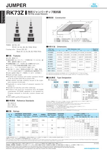
- For jumper chip resistors, refer to RK73Z series.
Catalog excerpts
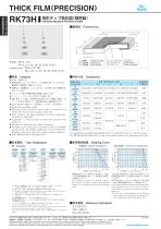
角形面実装抵抗器 Flat Chip Resistors THICK FILM PRECISION 角形チップ抵抗器 精密級 Flat Chip Resistors (Precision Grade) 有しています。 テーピング等の各種自動実装機に対応します。 リフロー、フローはんだ付けに対応します。 端子鉛フリー品は、欧州RoHS対応です。電極、抵抗、ガ ラスに含まれる鉛ガラスは欧州RoHSの適用除外です。 AEC-Q200に対応 データ取得 しています。 1Fを除く Small size and light weight. E xcellent heat resistance and weather resistance are ensured by the use of metal glaze thick film. High stability and high reliability with the triple-layer structure of electrode. Applicable to various kinds of automatic mounters for taping, etc. Suitable for both flow and reflow solderings. P roducts with lead free termination meet EU-RoHS requirements. EU-RoHS regulation is not intended for Pb-glass contained in electrode, resistor element and glass. AEC-Q200 qualified (Exemption 1F). ■品名構成 Type Designation 例 Example 寸法が異なります。 d” “ 寸法0.4 mm −0.1 0.2 ※1 RK73H 2H and RK73H 3A are also still available (different d” “ dimensions=0.4 mm) −0.1 ■負荷軽減曲線 Derating Curve 周囲温度 Ambient temperature 定格電力 Power Rating 端子表面材質 Terminal Surface Material 二次加工 Taping 公称抵抗値 Nominal Resistance 抵抗値許容差 Resistance Tolerance TX4mm width 1mm pitch plastic embossed TA1mm pitch press paper TBL・TC・TCM 2mm pitch press paper TPL・TP 2mm pitch punch paper TD4mm pitch punch paper TE4mm pitch plastic embossed BKBulk 端子部温度 Terminal part temperature 金めっき電極品は、1E、1J、2A 10Ω〜1MΩ で対応しております。 仕様が若干異なりますので、弊社までご相談ください。 1F、1H、W2H、W3Aは端子表面材質Tのみを対応致します。 P roducts with gold plated electrodes are also available with 1E, 1J and 2A types 10Ω〜1MΩso please consult with us. , ※3 ith type 1F, 1H, W2H, W3A only T is available as the terminal surface W material. 端子表面材質は鉛フリーめっき品が標準となります。 環境負荷物質含有についてEU-RoHS以外の物質に対するご要求がある場合に はお問合せください。 テーピングの詳細については巻末のAPPENDIX Cを参照してください。 The terminal surface material lead free is standard. Contact us when you have control request for environmental hazardous material other than the substance specified by EU-RoHS. For further information on taping, please refer to APPENDIX C on
Open the catalog to page 1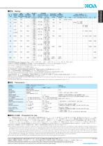
抵抗温度 定格 定格 定格電力 係数 周囲温度 端子部温度 Power Rated Ambient Rated Terminal T.C.R. Rating Temp. Part Temp. (×10−6/K) ±200 0.03W 70℃ — ±250 ±200 0.05W 70℃ — ±400 ±100 0.1W 70℃ 125℃ ±200 0.1W 0.125W 使用温度範囲 Operating Temperature Range :−55℃〜+125℃ (1F) 、−55℃〜+155℃ (1H・1E・1J・2A・2B・2E・W2H・W3A) 定格電圧は √ ̄ ̄ ̄ ̄ ̄ ̄ ̄ ̄ ̄ 定格電力×公称抵抗値による算出値、又は表中の最高使用電圧のいずれか小さい値が定格電圧となります。 Rated voltage= √ ̄ ̄ ̄ ̄ ̄ ̄ ̄ ̄ ̄ ̄ ̄ ̄ or Max. working voltage, whichever is lower. Power Rating×Resistance value ジャンパーチップはRK73Zシリーズを参照ください。 For flat chip jumper resistor, please refer to RK73Z series. ※4 RK73H1F (F:±1%) 及びRK73H1H (1Ω≦R≦9.1Ω、1MΩ≦R≦10MΩ) の公称抵抗値はE24となります。...
Open the catalog to page 2All KOA catalogs and technical brochures






Archived catalogs

- Temperature probe
- Resistance temperature sensor
- Compact temperature probe
- Wire-wound resistor
- Board-mount resistor
- Power resistor
- Housed resistor
- Thin-film resistor
- Thermistor
- Platinum resistive temperature sensor
- SMD resistor
- RoHS resistor
- Thick-film resistor
- Thin-film temperature sensor
- Voltage resistor
- High-power resistor
- High-voltage resistor
- Miniature fuse
- NTC thermistor
- Non-inductive resistor