HSG73P - THICK FILM FOR HIGH TEMPERATURE
1 /2Pages

HSG73P - THICK FILM FOR HIGH TEMPERATURE
1 /2Pages
Catalog excerpts
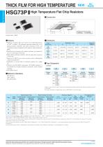
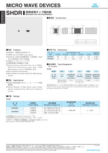
Flat Chip Resistors THICK FILM FOR HIGH TEMPERATURE High Temperature Flat Chip Resistors ■Construction L ① Protective coating ④ Inner plating ② Resistive lm ⑤ Outer plating ③ Inner electrode ⑥ Ceramic substrate Coating colorBlack ■Features ・ igh heat resistance that can be used even at high temperatures H of 155℃ or higher. The maximum operating temperature of Sn plating products compatible with solder mounting is 175℃, and Au plating products compatible with conductive glue mounting is 200℃. ・ xcellent heat resistance and weather resistance are ensured by E the use of metal glaze thick film. ・ igh stability and high reliability with the triple-layer structure H of electrode. ・ uperior to RK73 series chip resistors pulse withstanding S voltage and high power. ・ pplicable to various kinds of automatic mounters for taping, A etc. ・ Products meet EU-RoHS requirements. EU-RoHS regulation is not intended for Pb-glass contained in electrode, resistor element and glass. ・ EC-Q200 Tested. A Type Inch Size Code ■Type Designation Example HSG73P Product Code ■Reference Standards IEC 60115-8 JIS C 5201-8 EIAJ RC-2134C Nominal Resistance F4 digits J3 digits Resistance Tolerance TP2mm pitch punch paper TD4mm pitch punch paper BKBulk Contact us when you have control request for environmental hazardous material other than the substance specified by EU-RoHS. For further information on taping, please refer to APPENDIX C on the back pages. Rated Ambient Temp. Type Power Rating Rated Terminal Part Temp. Terminal Surface Material:T (Sn plating) T.C.R. Terminal Surface ×10−6/K F±1% Material:G E24 (Au plating) Terminal Surface Material:T (Sn plating) Terminal Surface Material:G (Au plating) Operating Temperature Range :−55℃175℃(Terminal Surface Material:T)、−55℃200℃(Terminal Surface Material:G) Rated voltage √ or Max. working voltage, whichever is lower. Power Rating×Resistance value ※1 If you use at the rated power, please keep the condition that the terminal of the resistor is below the rated terminal part temperature. Please refer to the derating curves based on the terminal temperature of right side on the next page. If any questions arise whether to use the“Rated Ambient Temperature”or the“Rated Terminal Part Temperature”in your usage conditions, please give priority to the“Rated Terminal Part Temperature” . For more details, please refer to“Introduction of the derating curves based on the terminal part temperature”on the beginning of our catalog. Specifications given herein may be changed at an
Open the catalog to page 1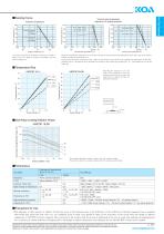
Terminal part temperature Applied to Sn plating products Terminal Surface Material T (Sn plating) Terminal Surface Material G (Au plating) For resistors operated at an ambient temperature of 70℃ or higher, the power shall be derated in accordance with the above derating curve. Percent rated power Percent rated power Percent rated power Flat Chip Resistors ■Derating Curve 125 135 Terminal part temperature ℃ 105 125 Terminal part temperature ℃ When the terminal part temperature of the resistor exceeds the rated terminal part temperature shown above, the power shall be derated according to the derating...
Open the catalog to page 2All KOA catalogs and technical brochures


Archived catalogs
- Temperature probe
- Resistance temperature sensor
- Compact temperature probe
- Wire-wound resistor
- Board-mount resistor
- Power resistor
- Housed resistor
- Thin-film resistor
- Thermistor
- SMD resistor
- Platinum resistive temperature sensor
- RoHS resistor
- Thick-film resistor
- Thin-film temperature sensor
- High-power resistor
- Voltage resistor
- High-voltage resistor
- Miniature fuse
- Non-inductive resistor
- NTC thermistor