
Catalog excerpts

I2S Output Digital Microphone The SPH0645LM4H-B is a miniature, low power, bottom port microphone with an I2S digital output. The solution consists of a proven high performance SiSonic™ acoustic sensor, a serial Analog to Digital convertor, and an interface to condition the signal into an industry standard 24 bits I2S format. The I2S interface simplifies the integration in the system and allow direct interconnect to digital processors, application processors and microcontroller. Saving the need of an external audio codec, the SPH0645LM4H-B is perfectly suitable for portable applications where size and power consumption are a constraint. Product Features: • • • • • • • • • • • • • High SNR of 65dB(A) Low Current of typ. 600µA I2S Output: Direct attach to µP Multi modes: standard >1MHz, 600uA / sleep <900kHz, 10uA Flat Frequency Response RF Shielded Supports Dual Microphones Ultra-Stable Performance Standard SMD Reflow Omnidirectional Zero-Height Mic™ Packaged in SPH 3.50 x 2.65 x 0.98 mm Typical Applications • • • Small portable devices: wearables Set-top boxes: TV, gaming, remote controllers Smart home devices, Internet of Things, Connected equipment Application Processor
Open the catalog to page 1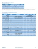
Absolute Maximum Ratings Table 1: Absolute Maximum Ratings Absolute Maximum Rating Input Current Short Circuit to/from DATA Stresses exceeding these “Absolute Maximum Ratings” may cause permanent damage to the device. These are stress ratings only. Functional operation at these or any other conditions beyond those indicated under “Acoustic & Electrical Specifications” is not implied. Exposure beyond those indicated under “Acoustic & Electrical Specifications” for extended periods may affect device reliability. Acoustic & Electrical Specifications Table 2: TEST CONDITIONS: 25 ±2°C, 55±20%...
Open the catalog to page 2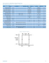
Microphone Interface Specifications Table 3: Table 2: TEST CONDITIONS: 25 ±2°C, 55±20% R.H ., VDD =1.8V, fCLOCK = 3.072 MHz with a .1uF decoupling capacitor across Vdd and GND, unless otherwise indicated Parameter Logic Input High Low→High Threshold High→Low Threshold Hysteresis Width Logic Output High SELECT (high) Select Input Clock Input Clock Duty Cycle Clock Rise/Fall Time (Input and Output) TIE Clock Jitter Time Interval Jitter on CLK line Output Load Data Format 18bit precision, the LSBs are filled with zeros Figure 1: Hysteresis Diagram
Open the catalog to page 3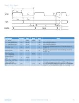
Figure 2: Timing Diagram CLK Pulse Width High WS typically synchronized with CLK falling, should be equal to tBIL WS typically synchronized with CLK falling, should be equal to tBIH Data Delay from CLK Rising Edge Receiver Setup time Transmitter Hold Time Clock Rise Time Measured from VL to VH Performance is guaranteed only with SCK edge time <=3.75ns. For slower edge time, operation is guaranteed but performance degradation might be expected.
Open the catalog to page 4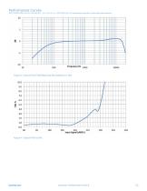
Performance Curves TEST CONDITIONS: 25 ±2°C, 55±20% R.H ., VDD =1.8V, fcLOCK = 3.072 MHz with .1uF decoupling capacitor, unless otherwise indicated Figure 3: Typical Free Field Response Normalized to 1 kHz
Open the catalog to page 5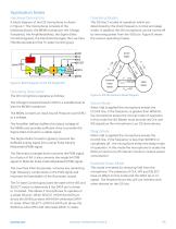
Application Notes Hardware Description A block diagram of the I2S microphone is shown in Figure 7. The microphone consists of the following blocks, the MEMS transducer, the Charge Pump(red), the Amplifier(yellow), the Sigma Delta Convertor(green), the Decimator(orange), the Low Pass Filter(turquoise),and theTri-state Control (gray). -AMP>- YA^> 1 -Oo- STATE -►DATA Figure 5: Block Diagram of the I2S Digital Mic Operating Description The I2S microphone operates as follows: The Charge Pump(red) boosts VDD to a suitable level to bias the MEMS transducer. The MEMs converts an input Sound...
Open the catalog to page 6
Interface Description The SPH0645LM4H microphone operates as an I2S slave. The master must provide the BCLK and WS signals. The Over Sampling Rate is fixed at 64 therefore the WS signal must be BCLK/64 and synchronized to the BCLK. Clock frequencies from 2.048Mhz to 4.096MHz are supported so sampling rates from 32KHz to 64KHz can be had by changing the clock frequency. The SEL pin determines when the microphone drives the Data pin. When SEL=H the Data pin is driven when the WS=H, otherwise it is tri-stated (high impedance). When operating a single microphone on an I2S bus, a pull down...
Open the catalog to page 7
System Connection’s Cont’d Figure 8, Shows how two I2S Microphones can be connected on a single I2S bus. R41–R44 are included to either dampen or terminate their respective traces. If the traces are electrically long then they should be controlled impedance traces with impedance in the 50-120 Ohm range. Electrically long traces are when the length of the trace (in inches) is => 2 times the rise/fall time (in nS). Even if the traces are not electrically long, R41-R44 can be used as dampening resistors (27-51 Ohms) to improve signal integrity by reducing overshoots and ringing caused by stray...
Open the catalog to page 8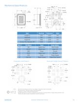
Mechanical Specifications niCK ARIA Example Land Pattern Example Solder Stencil Pattern Notes: Pick Area only extends to 0.25 mm of any edge or hole unless otherwise specified Dimensions are in millimeters unless otherwise specified Tolerance is ±0.15mm unless otherwise specified Detailed information on AP size considerations can be found in the latest SiSonic™ Design Guide application note Further optimizations based on application should be performed
Open the catalog to page 9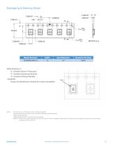
Packaging & Marking Detail "S": Knowles SiSonic™ Production "E": Knowles Engineering Samples "P": Knowles Prototype Samples Unique Job Identification Number for product traceability Notes: Dimensions are in millimeters unless otherwise specified. Vacuum pickup only in the pick area indicated in Mechanical Specifications. Labels applied directly to reel and external package. Shelf life: Twelve (12) months when devices are to be stored in factory supplied, unopened ESD moisture sensitive bag under maximum environmental
Open the catalog to page 10All Knowles Electronics catalogs and technical brochures
-
SPW2430HR5H-B Surface mount MEMS
11 Pages
-
SPA2629LR5H Surface mount MEMS
11 Pages
-
SPH0642HT5H-1 Surface mount MEMS
11 Pages
-
SPH0611LR5H-1 Surface mount MEMS
11 Pages


