- Catalogs
- KML Linear Motion Technology GmbH
- LineTech LM
LineTech LM
1 /44Pages

LineTech LM
1 /44Pages
Catalog excerpts
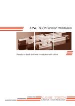
CONSULTING ENGINEERING MANUFACTURING LINE TECH linear modules Ready to built-in linear modules with drive
Open the catalog to page 1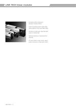
LINE TECH | – Anodized profile, produced in extrusion molding method – Linear rail guiding system (LM3–LM5), roller guides for minor load (RM3–RM5) – Actuation by ball screw, high-helix lead screw or toothed belt – Optional inductive or mechanical limit switches – AC servo drives or step motors, appropriate continuous or linear path control LINE TECH linear modules
Open the catalog to page 2
| LINE TECH Table of contents page/s – Design fundamentals____________________________________________________4 – Designation system_ ____________________________________________________5 – Notices for the product selection: - Drives______________________________________________________________6–7 - Mounting conditions__________________________________________________8–9 - Limit switches________________________________________________________10 – Load rates____________________________________________________________11 – Dimension drawings - LM3/RM3 (Size 65)_ ______________________________________________...
Open the catalog to page 3
LINE TECH | LINE TECH linear modules Design fundamentals LINE TECH linear modules LINE TECH linear modules are of modular conception, ready to built-in linear carriages with drive unit. A linear rail guide with two guiding carriages (LM3–LM5) or a roller guide with four or six rollers (RM3– RM5) are used as guiding elements. The drive unit preferably consists of ball screws or toothed belts. With little axial load, also high-helix lead screws “Speedy” can be used. The guidance as well as the actuation are protected by a steel strapping (LM3– LM5) or by the drive belt (LM3–LM5, RM3–RM5) against...
Open the catalog to page 4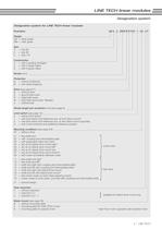
| LINE TECH Designation system for LINE TECH linear modules Examples: LM 3 . 2 . 0500 B R 016 . 1 . 02 . 0 F Design LM = linear guide RM = roller guide Size 3 = size 65 4 = size 80 5 = size 110 Construction 2 = with 2 guiding carriages 4 = with 4 guide rollers 6 = with 6 guide rollers Stroke (mm) Protection N = without protection B = with steel strapping Drive (see page 6/7) N = without drive S = ground ball screw R = rolled ball screw W = high-helix lead screw “Speedy” Z = toothed belt Stroke length per revolution [mm] (see page 6) Limit switch (see page 10) 0 = without limit switch 1 = with...
Open the catalog to page 5
LINE TECH | Drive Size Execution 1) Stroke range Positioning diam. x pitch accuracy [mm] [mm] [ìm/mm] Ball screw rolled rolled elective LM3 16x5, 16x10, 16x16 2000 standard: 130/300 LM4 2 0x5, 20x20, 16x50 3000 optional: 52/300 LM5 32x5, 32x10, 32x32 3000 2 3/300 High-helix lead screw «Speedy» LM3 16x25, 16x90 2000 2 00/300 LM4 2 4x40, 18x100 3000 2 00/300 LM5 30x50, 34x80 3000 2 00/300 Toothed belt, circumferential LM3 GT 5/25 155 mm/U 7600 2 00/1000 RM3 GT 5/25 155 mm/U 7600 2 00/1000 LM4 GT 5/40 2 05 mm/U 7500 2 00/1000 RM4 GT 5/40 2 05 mm/U 7500 2 00/1000 LM5 ST 8/50 2 96 mm/U 7400 2 00/1000...
Open the catalog to page 6
LINE TECH | Mounting condition The LINE TECH positioning systems can be purchased in various mounting conditions (picture 1 to 10). Depending on the drive selection there are different standard configurations available. For the dimensions see page 36. LINE TECH linear modules Selection evidence Picture 2: Free shaft end right hand side (Mounting condition 11) Picture 4: Screw drive with coupling and intermediate plate (Mounting condition 02) Picture 3: Free shaft end left hand side (Mounting condition 12) Picture 1: Free shaft end straight (Mounting condition 01)
Open the catalog to page 8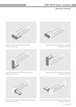
| LINE TECH LINE TECH linear modules Selection evidence Picture 7: Screw drive with lateral drive mount bottom (Mounting condition 07) Picture 8: Screw drive with lateral drive mount top (Mounting condition 06) Picture 5: Screw drive with lateral drive mount left (Mounting condition 05) Picture 6: Screw drive with lateral drive mount right (Mounting condition 04) Picture 9: Belt drive left with coupling and intermediate plate (Mounting condition 14) Picture 10: Belt drive right with coupling and intermediate plate (Mounting condition 13)
Open the catalog to page 9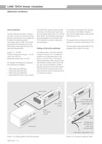
LINE TECH | 10 Limit switches The limit switches are used in conjunction with a control unit to limit the stroke (prevent overrunning of the carriage) and to define the reference position. The widely used and LINE TECH standard inductive limit switches are of the PNP-break contact type and show the following characteristics: Supply: 10…30 VDC Current consumption off-load: < 10 mA Load: max. 200 mA Mechanical switch-ratio: 0.4mm On request the following non standard limit switches are available: – PNP-make type (PNP-NO) – NPN-break type (NPN-NC) – NPN-make type (NPN-NO) – Mechanical limit switch...
Open the catalog to page 10
LINE TECH | 12 LINE TECH linear module LM3/RM3 Size 65 Detailled table of content page(s) – Dimension drawings LM3/RM3 (size 65): - LM3.2 with linear rail guiding system and screw drive_______________________13 - LM3.2 with linear rail guiding system and toothed belt drive_ ____________ 14–15 - RM3.4 with roller guides (with 4 rolls) and toothed belt drive_____________ 16–17 - RM3.6 with roller guides (with 6 rolls) and toothed belt drive_____________ 18–19
Open the catalog to page 12
13 | LINE TECH 33 28 246 28 25 28 52,5 85 11 4x M4x8 65 4x M6x12 70 LM 30 L 190 35 ø10 h6 43 85 6 ø38 h6 Stroke Nominal size Dimensions Designation L LM Screw length Length steel strapping Weight [mm] [kg] LM3.2.____ Stroke + 360 L – 58 L + 25 L – 18 4,6 kg + 0,65 kg/100 mm Stroke LINE TECH linear module LM3.2 with linear rail guiding system and screw drive
Open the catalog to page 13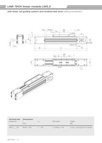
LINE TECH | 14 33 65 85 206 19,5 190 19,5 8 52,5 85 4x M4x8 95 L M 95 L 40 43 26 ø 38 H7x1.5 46 11 20 50 50 50 8x M5 ø 15 h9 33 4x M5x8 65 LINE TECH linear module LM3.2 with linear rail guiding system and toothed belt drive (without protection) Nominal size Dimensions Designation L LM Belt length Weight [mm] [kg] LM3.2.____NZ Stroke + 435 L – 190 2 x Stroke + 730 4,5 kg + 0,60 kg/100 mm Stroke Stroke
Open the catalog to page 14All KML Linear Motion Technology GmbH catalogs and technical brochures
 LMS E
LMS E11 Pages
 LMS E2
2 Pages
 LMS V
LMS V2 Pages
 product overview
4 Pages
 Image Brochure
16 Pages
 System solutions from KM
8 Pages
 KML Image
16 Pages
 System Solutions from KML
8 Pages


Archived catalogs
 Line Tech PS
68 Pages
 C-Lube Linear Way
155 Pages
 IKO TU Units
62 Pages
- Cylinder
- LIMING positioning stage
- Hydraulic cylinder
- LIMING linear positioning stage
- Servo-motor
- Pneumatic cylinder
- Motorized positioning table
- Turntable
- LIMING precision positioning stage
- AC servo-motor
- Electric rotary table
- Industrial cylinder
- LIMING 1-axis positioning stage
- IP65 servomotor
- Electric cylinder
- Linear axis
- Compact positioning table
- 2-axis positioning table
- Ultra-compact servomotor