- Catalogs
- KML Linear Motion Technology GmbH
- IKO TU Units
IKO TU Units
1 /62Pages

IKO TU Units
1 /62Pages
Catalog excerpts
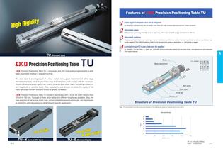
Features of Precision Positioning Table TU 1 2 3 Extra rigid U-shaped track rail is adopted. 4 Lubrication part C-Lube plate can be applied. By adopting a U-shaped track rail, the rigidity of the track rail under moment load and torsion is greatly increased. Abundant sizes precision positioning Table TU comes in eight sizes, with a track rail width ranging from 25 mm to 130 mm. Abundant options The type and lead of ball screw, motor type, sensor installation specifications, surface treatment specifications, bellows specification, etc. can be selected. Thus, Positioning Table TU can be used for...
Open the catalog to page 3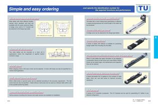
Precision Positioning Table Simple and easy ordering Just specify the identification number for the required functions and performance. TU The table with a motor folding back specification is effective in space-saving because the overall length of the table can be shortened. Slide tables with three different lengths, namely, short, standard, and long, are available with the same sectional shape. A bridge cover and /or X-Y bracket can be attached to the flange type table. A bridge cover can be attached to the flange type tables. Short, Standard and Long type Flange type A series of tables with...
Open the catalog to page 4
Identification Number and Specification Size Example of identification number 3 Table size For applications, see Table 1. TU 86 FG 89 A / Y029 G 10 S 0 0 R Q Table 1 25, 30, 40, 50, 60, 86, 100, 130 Combination of slide table shapes and sizes Shape Model TUC TU S TU G TUFC TUF TU FG TUYF TUES TU EF TU 25 Type TU 30 1 Model TU 40 2 Slide table shape TU 50 TU 60 Size TU 86 3 Size TU100 TU130 Part code Part code 4 Track rail length 4 Track rail length 5 Number of slide tables For applications, see Table 2.1, Specify the track rail length in cm. and Table 2.2. Motor code 5 Number of slide tables...
Open the catalog to page 5
Electric Device Motor code No symbolWithout motor A With motor 7 Motor type For applications, see Table 3. Type of motor 6, When Without motor no symbolis selected in item Motor attachment and coupling applicable to the selected motor are mounted at delivery. When Motor attachment and coupling are not necessary, please specify No symbol .See specification after C-1 Ball screw specificationsP.A-23 Ball screw code Motor code For applications, see Table 4. 9 Ball screw lead 4, 5, 8, 10, 20, 25 Ball screw leads Ball screw lead Motor brand Motor part number Motor code Model Motor part number Ball...
Open the catalog to page 6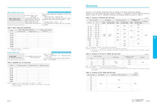
Accuracy Motor folding back specification Motor folding back code 13 Motor folding back For applications, see Table 5 No symbol Without motor folding back U Upward Motor folding back S Downward Motor folding back MMotor folding back to right H Motor folding back to left T Without Motor folding back unit P.A-37 When the Motor folding back is selected U, S, M or H is selected , 6 Specify With motor specify Ain item Only AC servo motor is applicable to sizes 60 and 86. WhenWithout Motor folding back unitis selected code T , 6 and 7 . SpecifyNo symbol in items For Low profile type, and Compact type,...
Open the catalog to page 7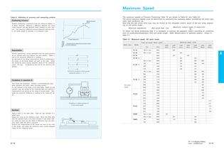
Maximum Speed Table 8 Definition of accuracy and measuring method Positioning accuracy L Perform positioning in sequence from the reference position in a certain direction. Measure a difference between the actual travel distance and the specified travel distance at each position. The maximum difference among measured distances within the stroke length is indicated in an absolute value. Measurement pitch Reference position Travel distance L The maximum speeds of Precision Positioning Table TU are shown in Table 9.1 and Table 9.2. The actual maximum speeds must be determined by examining the operating...
Open the catalog to page 8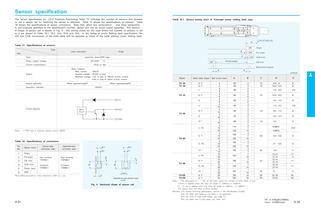
Sensor specification The sensor specification for Precision Positioning Table TU indicates the number of sensors and whether or not a sensor rail for fastening the sensor is attached. Table 17 shows the specifications of sensors. Table 18 shows the specifications of sensor connectors. Note that, when two sensorslimit and three sensorslimit, pre-originare specified in the identification number, sensor will not be wired unless specified. The sectional shape of sensor rail is shown in Fig. 4. The timing charts for the case where the number of sensors is set to 4 are shown in Table 19.1, 19.2, 19.3,...
Open the catalog to page 17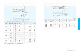
Table 19.4 Sensor timing chartmotor folding back with C-Lube plate Table 19.5 Sensor timing chart TUY TUE CW CCW CCW CW A ON End of track rail A ON C Pre-origin D CCW limit Model C TU 40 S, F G C TU 50 S, F G C, FC TU 60 S, F G, FG C, FC TU 86 S, F G, FG 4 8 4 8 4 8 5 10 5 10 5 10 5 10 20 5 10 20 5 10 20 10 20 10 20 10 20 Note 1The dimensions in are for the case where Remarks 1 For sensor mounting specification, specify in 2 For the table with bellows, this table is not 3 For the code of slide table shape, see page A-35 A 60 60 60 60 60 60 75 94 60 69 60 59 90 60 60 B 2 6 2 6 2 6 3 7 3 7 3 7...
Open the catalog to page 19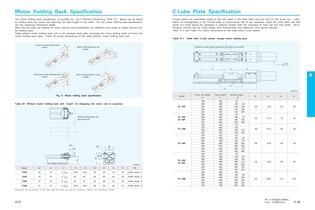
Motor Folding Back Specification C-Lube Plate Specification The motor folding back specification is available for Precision Positioning Table TU. Space can be saved by folding back the motor and reducing the total length of the table. For the motor folding back specification, see the respective dimension tables. Note that the track rail lengths of motor folding back specification are different from these of tables without motor folding back. Table without motor folding back unit is the resultant table after removing the motor folding back unit from the motor folding back table. Table 20 shows...
Open the catalog to page 20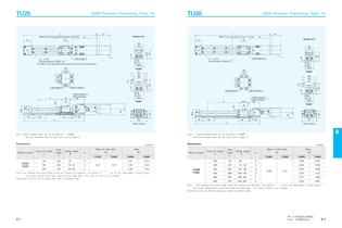
TU25 Precision Positioning Table TU L Minimum center distance between two slide tables in close contact 31 21 h 2 LM TU30 Precision Positioning Table TU Section A-A 67 h L Minimum center distance between two slide tables in close contact 39 2 LM 2 67 Section A-A 20 21 16 2 24 16 9 8.7 30 4-M3 depth 5.5 2 n1-2.9 5 counterbore, depth 2.7 12.4 8 9 24.9 1.8 6.7 1.6 4-M3 depth 4 2 n1-2.9 4.8 counterbore, depth 1.6 For M2.5 cross recessed head screws for precision equipment 25 28 20 14.9 9 12 29.9 TU25S 20 12 43 35 28 TU30S 3.5 22 8 S TU25F 28.6 35 20 A 35 31 L1 20 35 25 46 40 Note Model number unitmm...
Open the catalog to page 23All KML Linear Motion Technology GmbH catalogs and technical brochures
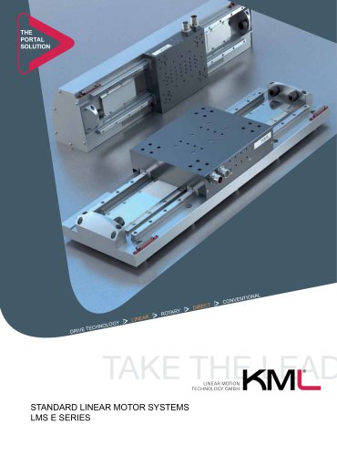 LMS E
LMS E11 Pages
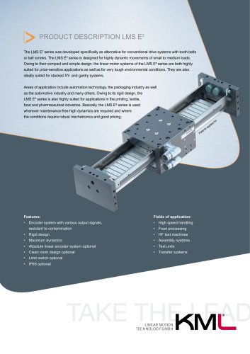 LMS E2
2 Pages
 LMS V
LMS V2 Pages
 product overview
4 Pages
 Image Brochure
16 Pages
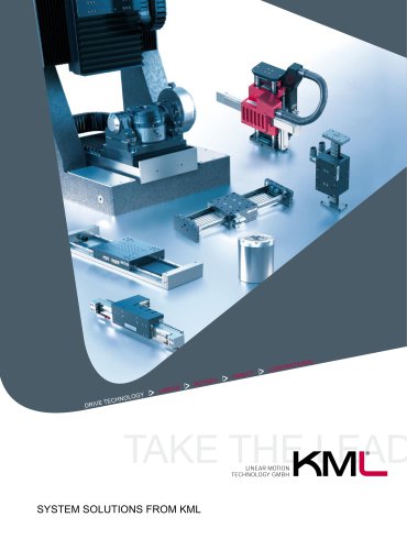 System solutions from KM
8 Pages
 KML Image
16 Pages
 System Solutions from KML
8 Pages


Archived catalogs
 Line Tech PS
68 Pages
 LineTech LM
44 Pages
 C-Lube Linear Way
155 Pages
- Cylinder
- LIMING positioning stage
- Hydraulic cylinder
- LIMING linear positioning stage
- Servo-motor
- Pneumatic cylinder
- Motorized positioning table
- Turntable
- LIMING precision positioning stage
- AC servo-motor
- Electric rotary table
- Linear motion system
- Industrial cylinder
- LIMING 1-axis positioning stage
- IP65 servomotor
- Electric cylinder
- Linear axis
- Compact positioning table
- 2-axis positioning table
- Ultra-compact servomotor