KPDS Process Sump Pump
1 /63Pages

KPDS Process Sump Pump
1 /63Pages
Catalog excerpts
INSTRUCTIONS ON INSTALLATION OPERATION AND MAINTENANCE FOR KIRLOSKAR MULTISTAGE PUMP TYPE “KPDS ALL MODELS” KIRLOSKAR BROTHERS LIMITED UDYOG BHAVAN, TILAK ROAD, PUNE - 411 00
Open the catalog to page 1
KIRLOSKAR BROTHERS LIMITED Udyog Bhavan, Tilak Road, Pune 411 002 (India) WARRANTY We warrant that the pump supplied by us is free from defective material and faulty workmanship. This warranty holds good for a period of 12 months from the date of commissioning of the equipment or 18 months from the date of despatch from our factory, whichever is earlier. Our liability in respect of any complaint is limited to replacing part/parts free of charge ex-works or repairs of the defective part/parts only to the extent that such replacement / repairs are attributable to or arise solely from faulty workmanship...
Open the catalog to page 2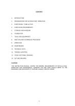
PRE-REQUISITES FOR SATISFACTORY OPERATION PUMP HOUSE / TANK LAYOUT PUMP HOUSE REQUIREMENTS ERECTION AND ASSEMBLING PROCEDURE 10. MAINTENANCE 11. TECHNICAL DATA 12. TROUBLE SHOOTING 13. CROSS SECTIONAL DRAWING 14. OUTLINE DRAWING CAUTION: THIS INSTRUCTION MANUAL COVERS THE GENERAL REQUIREMENTS OF INSTALLATION, OPERATION AND MAINTENANCE. HOWEVER THE END USER SHOULD REFER TO THE DRAWINGS AND DOCUMENTS IF SUPPLIED AGAINST SPECIFIC ORDER.
Open the catalog to page 3
INTRODUCTION KPD-S type sump pumps are manufactured to close tolerances and as per rigid specifications. However proper erection and maintenance is equally important to ensure proper service. The pump types are designated as KPD-S (delivery size in mm x nominal full diameter of impeller in cm). - e.g. KPDS 40/32 pump where 40 mm is delivery nozzle size of pump casing and 32 cm is nominal full diameter impeller. This booklet covers important guidelines and instructions on erection, operation and maintenance. These instructions should be followed carefully and failing to this may result in unsatisfactory...
Open the catalog to page 4
Liquid Inlet to the tank: The liquid should enter in the tank such that turbulence, high velocity and air entrainment is avoided at the suction of the pump. Suction tank: The tank should be designed so as to provide- Enough storage capacity to avoid sudden fluctuations in liquid levels, kinematic disturbances at the suction of the pump such as turbulence, eddies, vortices, air entrainment etc. Low velocity: The maximum liquid velocity of the liquid entering in the tank should not exceed 1 m/sec. Individual flow pattern: Where one tank houses more than one pumping sets, care must be taken to provide...
Open the catalog to page 5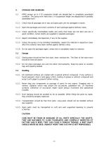
KPDS pumps up to 3 M suspension length are despatched in completely assembled condition. The pump with more than 3 m suspension length are despatched in partially assembled form. Check that all packages are in tact and open parts are not damaged in transit. Open the packages and check contents of each package against delivery notes. Check specifically intermediate shafts and verify that these are not bent and are in good condition. (when shafts are supplied in separate packages) Report immediately discrepancies, if any to the supplier. Unless the pump is to be installed immediately, repack the...
Open the catalog to page 6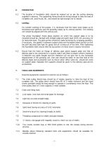
The location of foundation bolts should be marked out as per the outline drawing supplied in advance. The supporting frame should be strong enough to take the load of complete unit, axial thrust, etc. and should be rigid enough not to vibrate. Leveling : For smooth working of the pumps, it is necessary that the motor stool keeps up its horizontal level perfectly and the assembly keeps up its vertical position. The rotating unit should be aligned with the vertical axis. The whole foundation frame plane position on which the support plate is to be mounted should be checked with straight edge and...
Open the catalog to page 7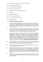
7.11.1 Files-triangular, half round and flat of different cuts and sizes. 7.11.2 Triangular scrapper, filler gauge. 7.11.3 Two sets of standard/ring spanners. 7.11.4 Set of wrenches and chain tang. 7.11.5 Adjustable spanner, screw drivers and 12”and 6”. 7.11.6 Allen keys. Steel rule and steel tape. Sets of taps and dies upto M16. Chisel, hammer, hack saw, vice etc. 7.11.10 Emery paper, cloth. 8. ERECTION/ ASSEMBLING PROCEDURE Follow the procedure given below in case of pumps to be erected for the first time or the pumps to be assembled after dismantling for overhauling. Clean all the parts thoroughly...
Open the catalog to page 8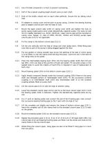
Use of thread compound is a must to prevent rust/seizing. Half of the screwed coupling length should come on each shaft. Ends of the shafts should rest on each other perfectly. Ensure this by taking colour seat. Fit adapter to casing cover and tee joint to pump casing. Connect the bearing flushing pipe to adapter and tee joint with the help of nuts. Mount the taper column pipe (143) on casing cover (220) and tighten the nuts on pump casing studs/casing cover studs diametrically opposite evenly. (for sizes 32 and 40 cm impeller diameters e.g. 40/32, 80/40 etc. taper column pipe will be mounted...
Open the catalog to page 9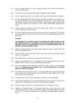
Mount the shaft sleeve (D.S.) with O-ring(523) and key (323). Mount circlip (486) to locate the shaft sleeve. Fit the pipe nut for rising pipe (338) along with gasket for pipe nut(680). Fix the adapter plate (461) to the stuffing box housing (238) with gasket in between. Lift the support plate (467) with the help of eye bolts screwed on it and mount it on top column pipe(132). Also mount stuffing box housing (233) on the support plate with gasket at the joint and clamp the stuffing box housing, support plate and top column pipe together with the help of bolts. Tighten diametrically opposite bolts...
Open the catalog to page 10
Mount the magnetic stand of dial indicator on the upper motor stool (290.1) and prop up the dial gauge on the top portion of the head shaft (185). Adjust the zero of dial gauge and tight the bearing nut (335) with the spanner in such a way that rotating unit is lifted by 1.0 to 1.5 mm. Tighten the lock nut (336) to lock the bearing nut. Fold one arm of lock washer (415.1) in the bearing cover slot and fold remaining arms on bearing nut (335). CAUTION: ENSURE THAT THE SHAFT ROTATES ABSOLUTELY FREE. Mount the pump half coupling (390) and tighten the set screw. Put coupling star (403) in between...
Open the catalog to page 11All Kirloskar catalogs and technical brochures
 Canned Motor P ump - i-CM
8 Pages
 KIRL OSK AR ROMAK PUMP - RMK
8 Pages
 KOS N Openwell Submersible Pumps
26 Pages
 NS Non Clog Submersible Pump
5 Pages
 SHS Solid Handling Sump Pump
16 Pages
 Mobile Pump Controller
4 Pages
 Eterna (Pressure Booster System)
12 Pages
 Fire Fighting System
1 Page
 HVACR System
24 Pages
 Condition Monitoring System
8 Pages
 Solar Pumping System
5 Pages
 RKB
RKB12 Pages
 SCT
SCT8 Pages
 UP / UPL / UPH / UP (T)
14 Pages
 DOMESTIC PRODUCT RANGE
26 Pages
 DB
DB12 Pages


