- Catalogs
- Kipp & Zonen
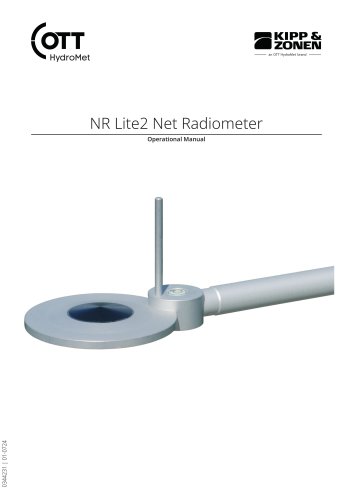
- NR Lite2 Net Radiometer
- Products
- Catalogs
- News & Trends
- Exhibitions
NR Lite2 Net Radiometer
1 /20Pages
NR Lite2 Net Radiometer
1 /20Pages
Catalog excerpts

Operational Manual
Open the catalog to page 1
OTT HydroMet B.V. Delftechpark 36 2628 XH Delft The Netherlands +31 15 2755 210 [email protected] www.otthydromet.com All rights reserved. All content is the intellectual property of OTT HydroMet. Reprinting, duplication and translation (even as excerpts) are only permitted with the prior written consent of OTT HydroMet. Subject to technical change.
Open the catalog to page 2
2 Order numbers and variant code_ 6 2.2 Accessories and spare parts_ 6 3 About this manual_ 7 3.1 General signs and symbols_ 7 4 General safety instructions_ 8 4.5 Risk of burns due to hot surfaces_ 8 4.7 Installation and maintenance at high places_ 9 6 Transport, storage, and unpacking_ 11
Open the catalog to page 3
11 Notes on disposing of old devices_ 17 12.1 Optical and electrical data_ 18
Open the catalog to page 4
The following items are included with delivery: - Bird stick - Test reports - Instruction sheet
Open the catalog to page 5
3 About this manual 3.1 General signs and symbols The signs and symbols used in the operational manual have the following meaning: Practical tip This symbol indicates important and useful information. Action ü Prerequisite that must be met before performing an action. 4 Step 1 ð Intermediate result of an action 4 Step 2 ð Result of a completed action List – List item, 1st level – List item, 2nd level 3.2 Explanation of warnings To avoid personal injury and material damage, you must observe the safety information and warnings in the operating manual. The warnings use the following danger levels:...
Open the catalog to page 7
The net radiometer is used to measure the net radiation balance between incoming and outgoing solar radiation. Any use of the product that does not comply with the intended use, be this intentional or negligent, is forbidden by the manufacturer. ► Use the product only as described in the operational manual. The equipment described in this manual must be installed, operated, maintained and repaired by qualified personnel only. ► Obtain training from OTT HydroMet if necessary. To avoid equipment damage and injury when handling the product, personnel are obliged to the following: ► Read the operational...
Open the catalog to page 8
When the product is installed and maintained at high places, special safety measures must be taken to avoid personal injury. ► Observe and follow the local safety regulations. ► Use suitable safety equipment. ► Inspect the safety equipment before use. ► Secure the person installing the product and the device used against falling down. ► Secure the instrument against falling down. The equipment meets the essential requirements of EMC Directive 2014/30/EU. FCC Part 15, Class "B" Limits This device complies with part 15 of the FCC Rules. Operation is subject to the following two conditions: 1. This...
Open the catalog to page 9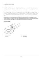
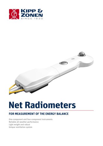
The NR Lite2 is a single-component net radiometer designed to measure the net radiation balance between incoming short-wave (UV) and far infrared (FIR) radiation from the sun and sky and the outgoing radiation from the ground. As the NR Lite2 is a single-component net radiometer, the short-wave (UV) and long-wave (FIR) components and the upwards and downwards components cannot be separated. Instead, the instrument directly measures the sum of the four net radiation components via the temperature differential. The result is converted to a single output signal. The instrument has an integral mounting...
Open the catalog to page 10
► Carefully remove the product from the packaging. ► Check that the delivery is complete and undamaged. ► If you find any damage or if the delivery is incomplete, then immediately contact your supplier or manufacturer. ► Keep the original packaging for any further transportation. ► Store within specified temperature ranges. ► Store in original box where possible.
Open the catalog to page 11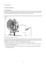
7 Installation 7.1 Mechanical installation 7.1.1 Choosing a site There should be no obstructions to the field of vision above the instrument’s sensor element. If this is not possible, the location of the instrument must be chosen to ensure that obstacles do not rise by more than 5 degrees above the azimuth range between sunrise after the shortest night and sunset on the longest day. The 5 degrees correspond to a minimum distance from the instrument to the obstacle of 10 times the height of the obstacle: Minimum distance from instrument to obstacle The minimum distance is important for measuring...
Open the catalog to page 12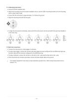
► Screw in the bird repellent stick. ► Attach the mounting rod at the chosen installation site or use the CMB1 mounting bracket to fix the mounting rod to a mast, pole or wall. ► Ensure that the instrument is approximately 1.5 m above the ground ► Align the mounting rod with the next pole. ► To align the instrument horizontally, rotate and tilt the instrument until at least half of the spirit level bubble is in the inner ring. ► Connect the instrument to a data logger or voltmeter. ► If using a data logger, connect the red wire with data logger terminal configured for the differential high and...
Open the catalog to page 13
The frequency of cleaning is dependent upon the local weather and environmental conditions. The following maintenance intervals are recommended: Interval Acitivity Performed by At least after 6 months ► Clean the absorber surfaces carefully with a lint-free Operator cloth and mild detergent or alcohol. Avoid abrasive materials and harsh chemicals. ► Check if the sensor is properly leveled. ► Check the conditions of the bubble level and ensure if its functional. ► Conduct a thorough visual inspection to detect any physical damage or signs of wear. ► Inspect all mechanical connections for tightness...
Open the catalog to page 14
If the instrument does not work properly and the problem is not clear, perform an "upside-down test" as follows: A lamp is available as a source of solar and far infrared radiation. - The elevation of the sun is more than 45 degrees above the horizon. - Weather conditions are stable and cloudless. ► Measure the output in the normal position. ► Record the measured values when the signals have stabilized, i.e. after about 3 minutes. ► Rotate the instrument 180 degrees, so that the upper and the lower sensors are now in the reverse orientation as to the previous position. ► Measure the output again....
Open the catalog to page 15All Kipp & Zonen catalogs and technical brochures
 Net Radiometers
4 Pages
 Pyranometers
8 Pages
 SP Lite2 Silicon Pyranometer
2 Pages
Archived catalogs
 SP Lite2 Silicon Pyranometer
2 Pages
 CGR Pyrgeometers
4 Pages
 UV Radiometers
4 Pages
 Brewer MKIII
4 Pages
 Sun Trackers
2 Pages
 RaZON+
4 Pages
 RT1
RT12 Pages
 Pyranometers
8 Pages
 SP Lite2
2 Pages
 AirShield Handout
2 Pages
 AMPBOX
2 Pages
 Pyrgeometers
4 Pages
 CM 121 Shadow Ring
2 Pages
 Albedometers
2 Pages
 SMP10 Pyranometer
2 Pages
 RaZON
RaZON4 Pages
 AirShield® DNI
2 Pages
 Newsletter 44
16 Pages
 CNR series
2 Pages
 Solar Monitoring Stations
24 Pages
 METEON 2.0
1 Page
 Albedometers
2 Pages
 CM 4 Pyranometer
2 Pages
 CMA Albedometers
2 Pages
 Net Radiometers
4 Pages
 Data Loggers
4 Pages
 LAS MkII
4 Pages
 AMPBOX Signal Amplifier
2 Pages
 Ventilation Unit - CVF4
2 Pages
 PV soiling monitoring
2 Pages
 PQS 1 PAR Quantum Sensor
2 Pages
 KippZonen_RT1_hand-out
2 Pages
 Kipp & Zonen Product Catalogue
92 Pages
 KippZonen Sun Trackers
4 Pages
 CA 2 Laboratory Thermopile
2 Pages
 Pyrheliometers
4 Pages
 Broadband UV Radiometers
4 Pages
 SP Lite2 Silicon Pyranometer
2 Pages
 LAS MkII Scintillometer
4 Pages
 The New CMP10
2 Pages
 SOLYS Gear Drive sun tracker
2 Pages
 Newsletter 45
8 Pages
 Newsletter 43
12 Pages
 DustIQ - Brochure
2 Pages
 KZ Sun Tracker
2 Pages
 CNR 1 Net Radiometer
2 Pages


- Connector
- Electrical cable
- Data connector
- Temperature probe
- Data logger
- Resistance temperature sensor
- Measuring machine
- Temperature datalogger
- Electrical data cable
- Flexible cable
- Flexible electrical cable
- Signal amplifying integrated circuit
- Waterproof temperature sensor
- USB datalogger
- IEC electrical cable
- Current connector
- Data-logger with screen
- Wireless datalogger
- Flame-retardant cable
- Datalogger without display