
- Catalogs
- Kikusui Electronics
- KFM2150 System

KFM2150 System

KFM2150 System
- Impedance measurement range: 10 mHz to 20 kHz.
- Operating voltages: 1.5 V to 150 V.
- Parallel operation of multiple PLZ-4W units for increased capacity.
- Adjustable AC current measurement from 0.1% to 10% of DC load current.
- Standard low voltage protection and external interfaces (RS-232C, GPIB, USB).
Catalog excerpts

Internet http://www.kikusui.co.jp/ FC Impedance Measurement System Fuel Cell Impedance Measurement System Capable of measuring impedance in the frequency range from 10 mHz to 20 kHz (KFM2150). Capable of IR measurement with the current interrupt method (KFM2150). For a load unit, enables selection and use of a Kikusui electronic load unit suitable to the power capacity of the Provides 32-channel inputs (KFM2151). By connecting multiple KFM2151 in parallel, up to 160 channels can be Capable of not only current monitoring but also impedance measurement (KFM2151).
Open the catalog to page 1
Supports cell types ranging from single cells of several hundreds of amperes to stack fuel cells of several kilowatts. The FC impedance meter KFM2150 cannot be used alone. It needs to be combined with a Kikusui PLZ-4W series electronic load unit, and be calibrated. KFM2150 SYSTEM 1000-01 bench top type Upper unit: KFM2150 Lower unit: PLZ1004W Fuel cell impedance measurement system KFM2150 SYSTEM The fuel cell impedance measurement system is configured with an FC impedance meter KFM2150 and a Kikusui PLZ-4W series electronic load unit. Thus, the impedance measurement system can be configured to...
Open the catalog to page 2
System lineup and main specifications Specifications Model Impedance meter Units configuring the system Electronic load unit Operation modes: constant current (CC) + constant voltage (CV) PLZ164WA (1 unit) Rating Operating voltage Rack mount type Rack mount type Rack mount type Rack mount type Rack mount type Rack mount type Constant current mode (CC) Ammeter display Constant voltage mode (CV) Allowable ranges (A)/Resolution (mA) Allowable ranges (V)/Resolution (mV) Voltmeter display 10-V range (V) 100-V range (V) 150-V range (V) [Accessories] Instruction manual × 1, power cord × 1, sensing wires...
Open the catalog to page 3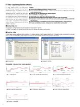
FC Tester (supplied application software) FC Tester enables control of the KFM system from a PC, conducting tests for acquiring the characteristics of fuel cells, such as I-V characteristics, constant current characteristics, and Cole-Cole plot and other data with the current interrupt method and the AC impedance method. It also enables tests to be conducted in the order they are specified. When combined with the FC scanner KFM2151, it can support measurement of the impedance of each cell while switching from one cell to another in sequence. Features n Provides startup and shutdown sequences...
Open the catalog to page 4
Executive This program executes characteristic tests in accordance with the test condition file created with Condition Editor. It monitors each measurement at the start and stop of a test and during the test. It can graphically represent voltage, current, and impedance trends in real time. Cole-Cole plot window (3D graphic display) [Recommended operating environment] The following are the hardware and software requirements for using the supplied application software. IBM-PC/AT or compatible, with a 600-MHz Pentium III microprocessor or equivalent or higher (Pentium 4 or equivalent or higher recommended)...
Open the catalog to page 5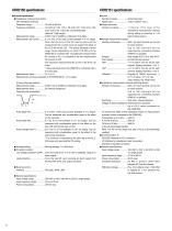
Inputs Number of inputs ����������������� 32 terminal pairs Rated input �������������������������� ±150 V (±200 V max.) Output terminals Number of outputs ��������������� 1 c h a n n e l . ( T h e i n p u t o f t h e impedance measurement channel during setting or scanning is 1/10 before being output.) Voltage measurement section Number of channels ������������� 32ch. An input terminal can be set for each channel. (Up to 160 channels can be supported by connecting multiple KFM2151 in parallel.) Ranges �������������������������������� Auto ranges of 2 V, 20 V, and 200 V Scan speed ��������������������������...
Open the catalog to page 6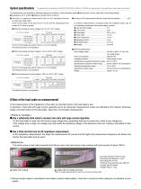
System specifications * This catalog contains the specifications of KFM2150 SYSTEM 1000-01 (KFM2150 + PLZ1004W) as a typical example. For the specifications of other systems, contact Kikusui.) The specifications are specified by following setting and conditions, unless otherwise stated: Temperature: 20°C to 30°C Relative humidity: 20%rh to 85%rh n Accuracy of impedance measurement with the AC impedance method (2-meter load cable used) If the current range on the load unit is H or M, and the measurement AC current is 0.5 Arms or greater. When the sensing end input voltage is 0 V to 10 V (10 V...
Open the catalog to page 7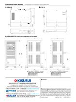
DirflBnSiOllcll OUtlillB dr3WinPS * For outside dimensions of the PLZ-4W series units, refer to their respective catalogs. ' KFM2150 SYSTEM (depth varies depending on the system) Systems to which these drawings apply Systems to which these drawings apply KIKUSUI ELECTRONICS CORPORATION 1 -1 -3, Higashiyamata, Tsuzuki-ku, Yokohama, 224-0023, Japan KIKUSUI AMERICA, INC.1-877-876-2807 www.kikusuiamerica.com Krfjffrioi'li 2975 Bowers Avenue, Suite 307, Santa Clara, CA 95051 1^9 '^'VEKSK? Phone : 408-980-9433 Facsimile : 408-980-9409 KIKUSUI TRADING (SHANGHAI) Co., Ltd. | www.kikusui.cn Room 216,Building...
Open the catalog to page 8All Kikusui Electronics catalogs and technical brochures
 TOS9300 Series
28 Pages
 Warning Light / Buzzer
52 Pages
 Calibration Equipments
52 Pages
 KHA Series
16 Pages
 KFM2005
4 Pages
 KFM2030
4 Pages
 PFX2500 Series
16 Pages
 PFX2000 Series
8 Pages
 PFX2000 Series Basic Package
4 Pages
 PFX2400 Series
8 Pages
 TOS6200A Ground Bond Tester
52 Pages
 TOS5200 Hipot Tester
8 Pages
 PLZ6000R
4 Pages
 TOS9213AS
2 Pages
 PCR-LE2 Series
28 Pages
 PWX series
12 Pages
 PBZ Series
20 Pages


Archived catalogs
 Electrical Safety Tester
40 Pages


- Power supply unit
- DC power supply
- AC/DC power supply
- Measuring device
- Benchtop analyser
- Switched-mode power supply
- Digital tester
- Compact power supply
- Tabletop power supply
- Generator
- Multimeter
- Voltage testing system
- Digital multimeter
- Benchtop tester
- Single-phase power supply
- Rack-mount power supply
- Programmable power supply
- Regulated power supply
- Power meter
- Laboratory tester