Catalog excerpts
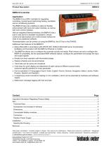
Product Description BMR410 Controller Application The BMR410 is a DDC controller for regulating, controlling, monitoring and optimizing heating, ventilation and air conditioning systems. The BMR410 also has a fieldbus to allow for flexible enhancement with input and output modules, as well as with room control modules. With an integrated Ethernet interface, the BMR410 has a built in web server to facilitate visualization, remote control and data backup over a web browser without the need of any additional software. Parameterization can be carried out using the BMRTool, the SI Tool or the PS4000. Additional main features of the BMR410: ■ Native BACnet® in accordance with DIN EN ISO 16484-5 (BACnet® server functionality); facilitates communication with the BMS by Ethernet or modem. ■ The BMRTool allows you to configure the controller quickly and easily. Plant macros are set to configure the BMR410 completely, set the associated BMR software objects, configure the parameters and assign the input and output signals. ■ Simple turn-knob operation with illuminated display ■ Weekly schedule and annual schedule ■ Trend data can be saves and visualized ■ Code keys for quick display and adjustment of plant values at different access levels; customer-specific plaintext for every parameter ■ Can be operated in 12 languages (Czech, Dutch, English, French, German, Hungarian, Italian, Latvian, Polish, Russian, Spanish and Swedish) ■ 3 closed-loop control circuits for heating or 2 for ventilation, which can be extended by hardware and software objects ■ Malfunction message logging with time and date
Open the catalog to page 1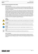
Product Description Important Information Regarding Product Safety Safety Instructions This data sheet contains information on installing and commissioning the product "BMR410". Each person who carries out work on this product must have read and understood this data sheet. If you have any questions that are not resolved by this data sheet, you can obtain further information from the supplier or manufacturer. If the product is not used in accordance with this data sheet, the protection provided will be impaired. Applicable regulations must be observed when installing and using the device....
Open the catalog to page 2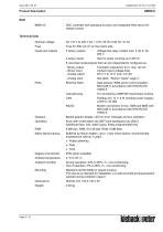
Product Description DDC controller with operating function and integrated Web server for remote control Technical Data Nominal voltage Fuse S1 630 mA (T) on the mains side Voltage-free relay contact max. 5 (3) A; AC 250 V Also for pulse counting up to 80 Hz 8 universal inputs/outputs that can be independently configured as: - Binary output - Binary input - Analog output - Analog input See table "Sensor Types", page 4. Data backup; WEB server communication; BACnet® in accordance with DIN EN ISO 16484-5 Cascade plug For connecting a BMF400 input/output module Fieldbus DC 12 V; 6 W (module...
Open the catalog to page 3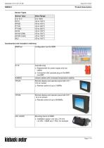
Sensor Types kieback neter
Open the catalog to page 4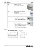
kieback neter
Open the catalog to page 5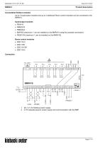
Product Description Connectable fieldbus modules Up to 3 Input/output modules and up to 3 additional Room control modules can be connected to the BMR410. Input/output modules ■ FBU410 ■ FBM(0)18 ■ FBM(0)24 ■ BMF400 (maximum 1 can be installed on the BMR410 using the cascade connection) ■ FBS51/04 (maximum 1 can be installed on the BMR410) Room control modules ■ DDC110-3 ■ DDC110S ■ DDC110-3S1 ■ DDC110-4 DC 12 V for fieldbus power supply Z179 cascade plug for power supply and communication with the BMF
Open the catalog to page 6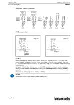
Product Description Sensor and actuator connection 0..10V DC Fieldbus connection Fieldbus When connecting the fieldbus, use a cable of at least type JY(St)Y 2x2x0.8 Lg: two x two wires, twisted to a pair with plastic insulation and an electrostatic shield with a wire diameter of at least 0.8 mm. Use a stranded pair of wires for the data lines (+ and -) and another free wire for the ground connection (0). At the end of the fieldbus (furthest point from the DDC controller), install a terminating resistor of about 180 ohms between both data lines (+ and -). The terminating resistor is included...
Open the catalog to page 7
Fieldbus Power Supply In the simplest case, the fieldbus module can be supplied with power from the BMR410. When JY(St)Y 2x2x0.8 Lg bus cables are used, the following maximum fieldbus lengths are possible: Tab. 1: Maximum fieldbus length per power supply By installing additional power supplies, you can use a fieldbus length of up to 2000 m. ■ Fieldbus Power Supply: DC 12 V; 6 W The BMF does not require any additional power supplies as it is supplied over the cascade plug and FBS modules always need to be supplied with external power as they require an AC 24 V power supply (the power supply...
Open the catalog to page 8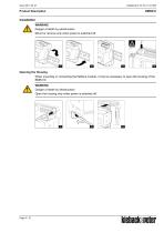
Product Description Installation WARNING Danger of death by electrocution Mount or remove only when power is switched off. Opening the Housing When mounting or connecting the fieldbus module, it may be necessary to open the housing of the BMR410. WARNING Danger of death by electrocution Open the housing only when power is switched off.
Open the catalog to page 9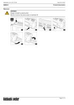
Product Description Removal WARNING Danger of death by electrocution Mount or remove only when power is switched off.
Open the catalog to page 10All Kieback & Peter catalogs and technical brochures
-
DDC4000 automation system
4 Pages
-
MD15 Small Actuator
8 Pages
-
Actuators and control valves
12 Pages
-
MF200 Emergency Actuator
38 Pages
-
MF201 Emergency Actuator
26 Pages
-
HRP22-V
6 Pages
-
HRP Heating Control Processor
16 Pages
-
Stellantriebe und Stellventile
60 Pages
-
DDC3000 Automation System
34 Pages
-
DDC4000 Automation System
26 Pages
-
LON Room Automation, Wireless
18 Pages
-
Transducers
24 Pages


